Technical Manual VERSION 2.0 -10-18-2018
73
7.2 Economizer applications
HANBELL screw compressor can be fitted with an additional middle connection for economizer operation. With this
form of operation, refrigeration capacity and also system efficiency can be improved by means of a subcooling circuit
or twostage refrigerant expansion.
Based on HANBELL extensive research a special design of the economizer connection has been developed so that
the connection causes no additional back flow losses during compression. As a result of this, compressor capacity is
fully retained in all operating conditions.
Please refer to Hanbell selection software for calculation of economizer capacity at different operating conditions.
Principle of operation
As opposed to the reciprocating operation of a piston compressor, the compression in a screw compressor takes place
only with one flow direction. When the rotors turn, refrigerant vapor is pressed into the rotor grooves by the opposing
rotor teeth and transported to end wall of the corresponding working space. In this phase, the volume is steadily
reduced and the vapor is compressed from suction pressure to condensing pressure.
The pressure at the additional middle connection is at a similar level to the intermediate pressure with a twostage
system. As a result of these features, a screw compressor of this design can be combined with an additional sub
cooling circuit or an intermediate pressure vessel (flash type subcooler) for twostage expansion. These measures
result in a clearly increased refrigeration capacity due to additional liquid subcooling, especially with highpressure
ratios. The power consumption of the compressor increases slightly compare to the additional work that takes place at
a better level of efficiency.
System with Economizer (subcooler)
With this form of operation, a heat exchanger (refrigerant subcooler) is used to subcooled liquid refrigerant. The sub
cooling is achieved by injecting a part of the refrigerant from the condenser through an expansion device in counter
flow into the subcooler, which then evaporates due to the absorption of heat. The superheated vapor is pulled into the
compressor at the Economizer connection and mixed with the vapor, which is already slightly compressed from the
evaporator.
The subcooled liquid is at condensing pressure with this form of operation, the pipeline to the evaporator does not
therefore require any special features, aside from insulation. The system can be generally applied. Figure 67 shows the
system with economizer, subcooler.
System with economizer (flash type)
The liquid subcooling is achieved with this form of operation by reducing the boiling point pressure in an intermediate
pressure vessel (flash type subcooler) arranged between condenser and evaporator. This physical effect leads to
the cooling of the liquid down to the boiling point, due to evaporation of part of the liquid. To stabilize the pressure of
the vessel, a regulator is used which at the same time controls the quantity of vapor flowing to economizer connection
of the compressor.
This form of operation gives the most economical thermodynamic performance due to direct heat exchanging. As the
intermediate pressure is reduced to the boiling point temperature this system should only be used with flooded
evaporators. Figure 68 shows the system with economizer, flash type subcooler.
Note:
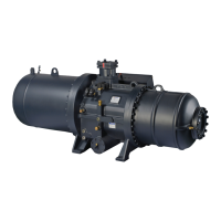
1. When economizer is used, it is recommended to install a
muffler before middlepressure returned gas port in
compression chamber to effectively mitigate pulsation noise in
middle pressure as shown in the drawing below.
2. A filter and check valve are also recommended to install
before ECO port of compressor.
Figure 68 Installation of ECO buffer