Technical Manual VERSION 2.0 -10-18-2018
74
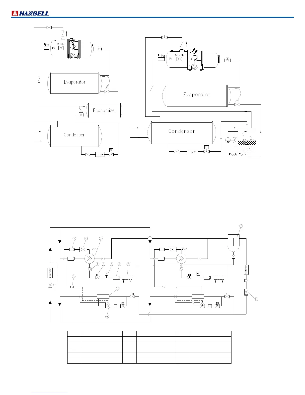
Figure 69 System with economizer (subcooler) Figure 70 System with economizer (flash type subcooler)
7.3 Parallel system applications
In the rack or parallel system, it is possible to happen the unequaldistribution of returned oil from the evaporator that
could cause low oil level in one or more of the compressors. Be sure to install the oil level switch inside each
compressors and oil flow switch installed in each oil return line to ensure the returned oil in each compressor with
normal oil level.
The basic design of the system is shown in Figure 69, twin compressor parallel system connections. The accessories
installed are the basic and if there are more applications or protection required, contact HANBELL or local
distributor/agent for more information or further confirmation.
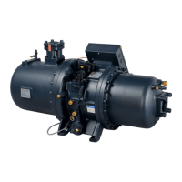
Figure 71 Parallel system with two compressors
Item
Description Item
Description Item
Description
1 Filter 6 Flow switch 11 Dryer
2 Compressor 7 Oil filter 12 Secondary cooler
3 Check valve 8 Oil cooler 13 Muffler
4 Sight glass 9 Expansion valve
5 Solenoid valve 10 Oil separator