Technical Manual VERSION 2.0 -10-18-2018
11
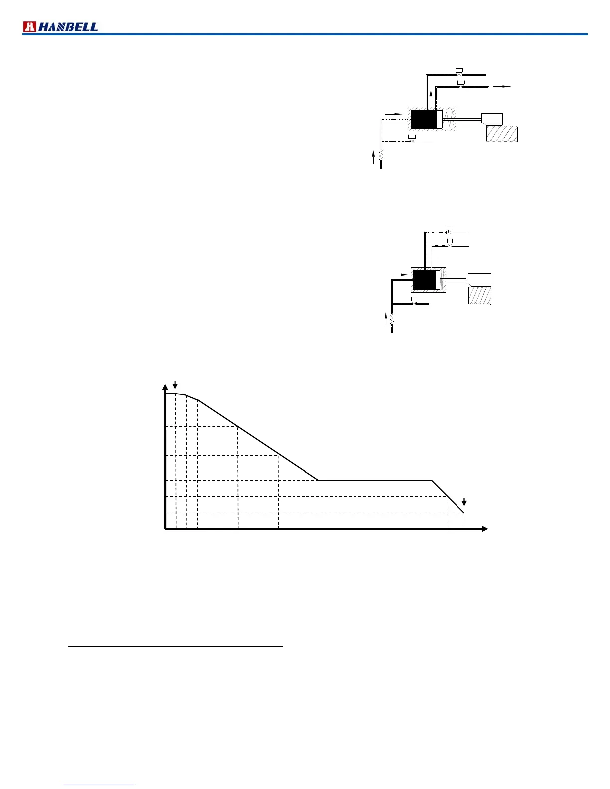
c. 75%/66% capacity
When SV75%/66% solenoid valve is energized, SV50% solenoid valve
will be deenergized simultaneously, the high pressure oil will push the
piston toward the position where a hole at exactly 75%/66% position
drains the oil back to the suction side and the piston will be held on
that position.
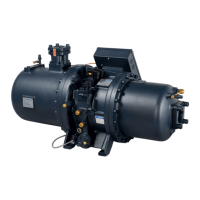
d. 100% full load
When all of two/three modulation solenoid valves are deenergized,
the highpressured oil flows into the cylinder continuously to push the
piston toward the suction side gradually until the slide valve touches
the end of the compression chamber and the piston also reaches its
dead end entirely where no bypass of compression gas occurred.
Therefore, full load is achieved.
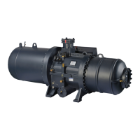
※ It is strongly recommend to start /stop compressors as per above illustration
Note: 1. Above T & T' should be determined by system designer’s experience and end user’s application.
2. Above t1 & t2 should be longer than 60 sec as recommended.
3. Capacity control must be kept at min% capacity for 1~3 min before start and for 60~90 sec before stop.
4. Start the compressor at min% and SV50% can be energized right after start.
2.8 Continuous (stepless) capacity control system
In continuous (stepless) capacity control system, solenoid valve SV2 (for loading) and solenoid valve SV1 (for
unloading) are equipped to inlet and outlet of piston cylinder respectively. These two solenoid valves are controlled by
chiller temperature controller or micro controller so refrigeration capacity can be modulated anywhere within min% ~
100%. Min% is recommended for start and stop only, not for longtermed operation.
It is very important for any controller to control loading and unloading in stable condition. For a smooth modulation,
HANBELL installs a capillary in loading oil line and an additional orifice valve in unloading oil line to avoid too fast
loading and unloading.
50%
Time
Set point + 2T
Set point + T
Set point (target)
Set point – T'
Stop
Chilled Water Temp
.
Figure 13.
Start / stop sequence and temperature / modulation of single
compressor
50%(66%) 75%(66%) 100%
t1 t2
75%
min%
1
~
3
min
min%
60~90 sec
SV50% OFF
(omitted for RC2100, 140 & 180)
SV75%/66% ON
SV25%/33% OFF
Figure 11 75%/66% Capacity
SV 25%/33% OFF
Figure 12 100% (Full load)
Capacity