Technical Manual VERSION 2.0 -10-18-2018
52
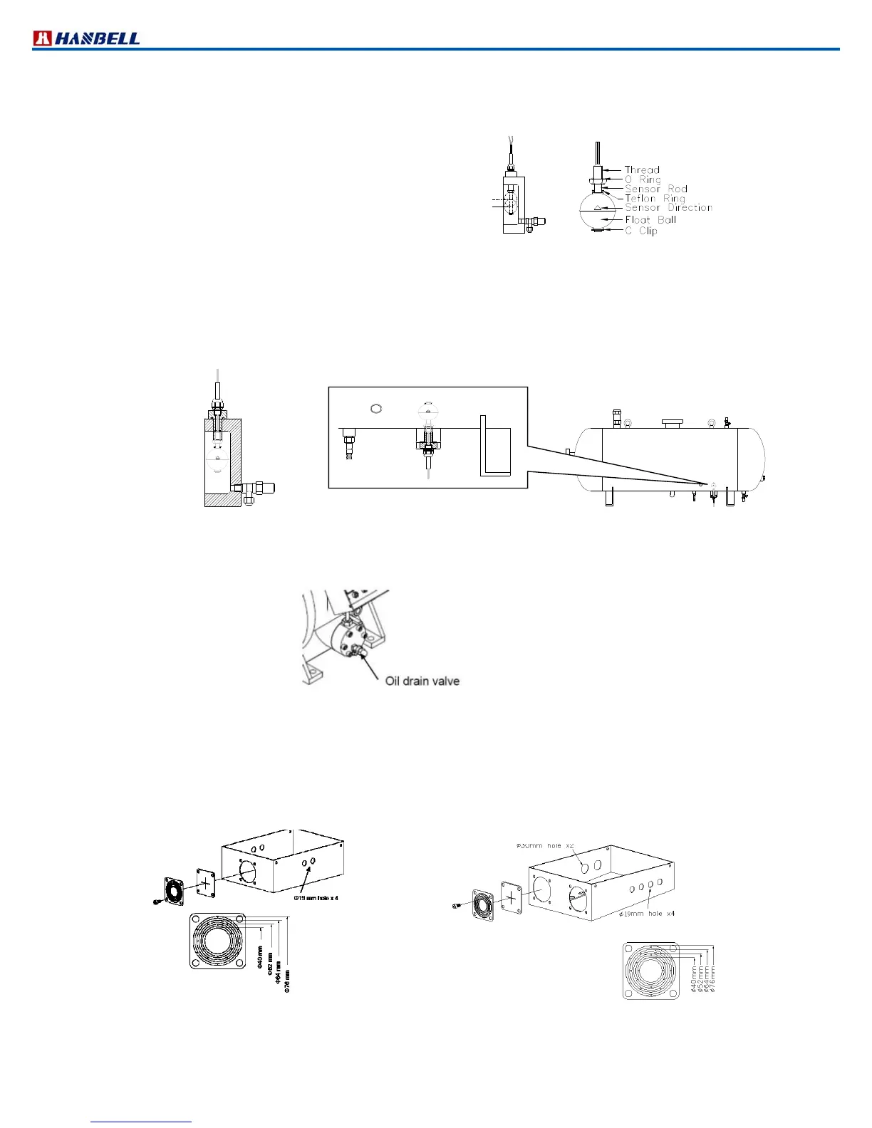
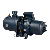
h. Oil level switch
There are 2 wires for the interlock to main control circuit or any micro controller’s independent circuit. To prevent from
oil level switch trip caused by oil foaming or surging in the sump, a time delay around 10 ~ 15 seconds is
recommended before shut down the compressor.
Max. contact capacity = 50W/SPST
Surge current = 0.5A
Max. voltage = 200V DC/ 240V AC
Max. current = 1A
Note:
1. On the float ball there is a triangle mark which tells you its sensor direction. Therefore, before you install an oil level
switch on a compressor or an external oil separator, please use the triangle mark as your reference before install
any oil level switch on the compressor or external oil separator.
2. Please check this triangle mark and modify the oil level switch if needed.
3. If you have any other question, don’t hesitate to contact with Hanbell representatives for help.
4. The illustration below show you the outside appearance of our oil level switch
Figure 33 Oil level switch on a compressor Figure 34 Oil level switch on an external oil separator
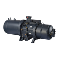
i. Oil drain valve
Oil drain valve is installed in compressor to drain out oil for maintenance.
Figure 35 Oil drain valve
j.IP54 cable box
Hanbell designs and makes the cable box which meets IP54 protection degree.
Dimensions of cable box and the size of opening in cable box (for motor power line and control power line) refer to the
drawing below
RC2100, RC2140, RC2180 cable box (Figure 36) RC2200, RC2230, RC2260, RC2300, RC2310, RC2
320, RC2340, RC2370, RC2410, RC2430, RC2470, RC2
510, RC2550, RC2580, RC2620 cable box (Figure 37)
Norm al Level
Low Level N.O.
N.C.
Figure 32 Oil level switch