29
Required Parts
• Fuselage w/ stabilizer • 5" rudder linkage
• 8-32 flange nut • Molded swivel link
• 4-40 locknut • Ball link for servo arm
• Ball link for swivel link
• 4-40 x 1/2" socket head screw
• 8-32 x 2
1
/
4
" control horn screw
Required Tools and Adhesives
• Drill • Drill bit: 1/16"
• Dental floss or string
• Aluminum servo arms
• Control horn ball ends
• 18" Servo Extensions (JRPA099)
The rudder requires a minimum of 100 ounce inch
of servo torque. In the prototype Extras we used a
JR8411SA servos with excellent results. Using servos
with less torque could result in blow back.
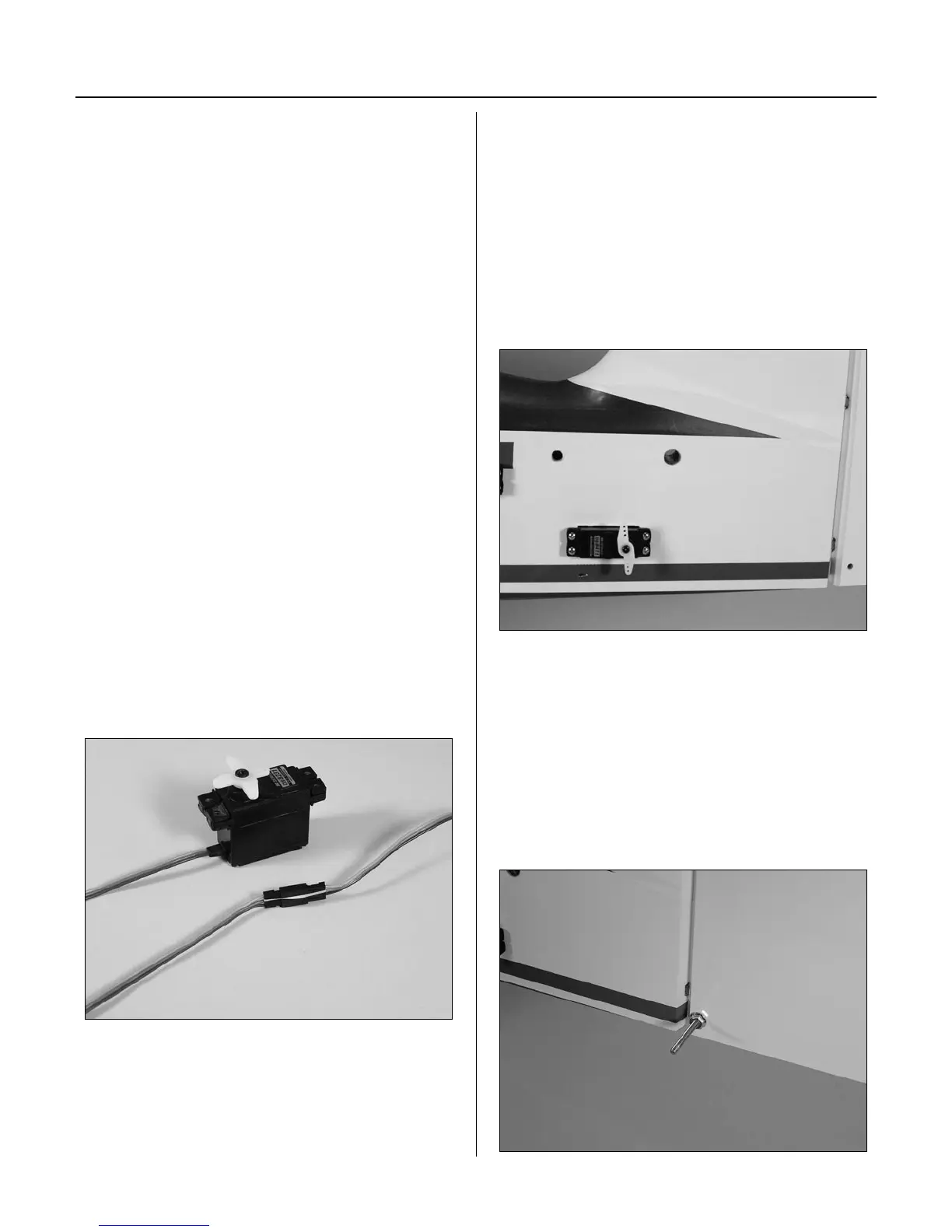
Step 1
Install an 18" servo extension onto the rudder
servo. Either tie the servo leads together, using a
commercially available connector, or use unwaxed
dental floss to secure the extension to prevent it from
coming loose during flight.
Step 2
Remove the covering from the fuselage for the rudder
servo location. Install the servo in the fuselage tail
section with the output shaft to the rear as shown in
the photo.
Step 3
Using the screws included with the servos, fasten
the servos in place. You may find it helpful to drill a
1/16" pilot hole before installing the screws.
Step 4
Mix a small amount of 30-minute epoxy and lightly
coat the inside of the hole in the rudder and the
8-32 x 2
1
/
4
" control horn screw. Slide the screw into
the hole from side opposite of the rudder servo. Wipe
away any excess epoxy on the wing and screw with
rubbing alcohol and a paper towel. Screw the
8-32 flange nut in place as shown. Allow the epoxy to
fully cure.
Section 8B – Rudder Servo Installation: DA-50