26
Required Parts
• Fuselage assembly
Required Tools and Adhesives
• Threadlock • Ruler
• 4-40 linkage • 8-32 flange nut (2)
• 4-40 locknut (2)
• 8-32 x 4" control horn screw
• 4-40 x 1/2" socket head screw (2)
The Extra 260 has two options for mounting the
rudder servo. For lighter engines, such as the
Saito™ 1.80 and 2.20, a pull-pull system is used. For
heavier engines, such as the DA-50, a tail mounted
servo is used.
The rudder requires a minimum of 100 ounce inch
of servo torque. In the prototype Extras we used a
JR8411SA servos with excellent results. Using servos
with less torque could result in blow back.
Step 1
Thread the 8-32 x 4" control horn screw into the
hole in the rudder and epoxy in place. Thread the
8-32 flange nuts onto the screw from both sides of
the rudder. Position the screw so it is centered in the
rudder. Use threadlock on the nuts to prevent them
from loosening during flight.
Step 2
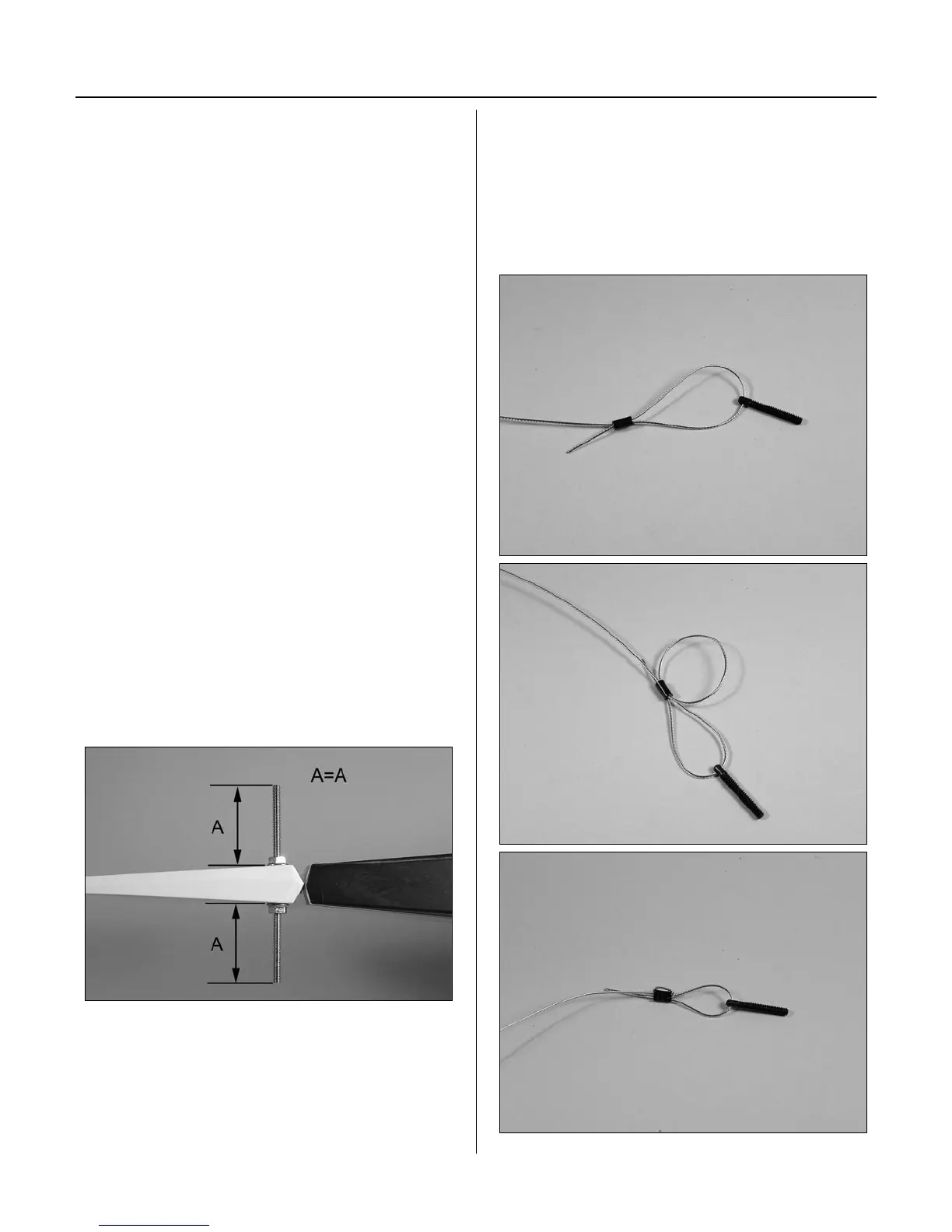
Cut the cable into two equal pieces. Prepare one
end of the pull-pull cable using the cable, threaded
cable end and crimp. The cable passes through the
crimp, through the threaded end, then back through
the crimp twice. Pull the excess cable tight and use a
crimping tool to complete the job.
Section 8A – Rudder Servo Installation: Saito