11
Note: The retract has been removed
from the aircraft for clarity. Do not
over-tighten the screw or the retract
will bind and not operate correctly.
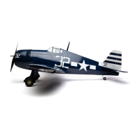
Step 11
With the retract extended, physically check to make
sure the retract does not move fore or aft by moving
the strut as shown in Step 10. Tighten the adjustment
screw in the front of the retract to eliminate any
play when in the down and locked position.
Step 12
If you notice that the retract has play when fully
retracted, it may be necessary to tighten the adjustment
screw on the retract to eliminate this. The screw
is located inside the retract, so it will have to be
removed from the aircraft to make this adjustment.
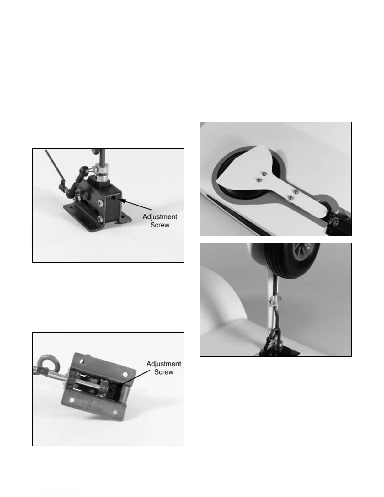
Step 13
The landing gear door is attached using two aluminum
brackets, four 3mm x 10mm screws, four 3mm washers
and four 3mm nuts. Draw a centerline down the backside
of the landing gear door to aid in alignment. Pre-drill the
landing gear doors for the screws using a 1/8" (3mm)
drill bit. Make sure the location of the aluminum brackets
does not interfere with the operation of the retracts.
Note: It is suggested to leave the
gear doors off when flying from
grass or other rough surfaces.
Step 14
Repeat Steps 8 through 13 to complete the
retract installation.
Section 1: Retract Linkage Installation
 Loading...