11 / 72
12. Trigger level.
1.5. Functional Check
Follow the steps below to perform a quick functional check to your oscilloscope.
1.5.1. Connect the oscilloscope
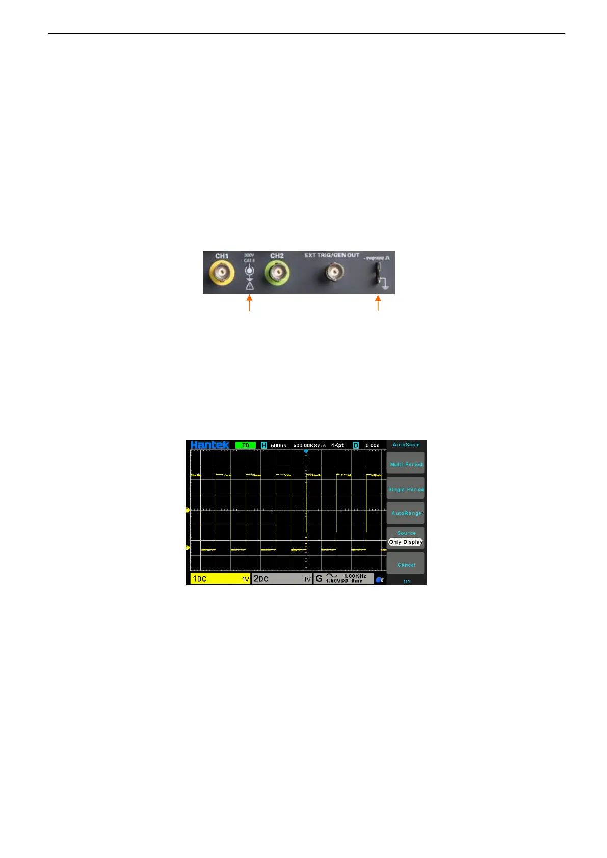
Set the switch on the probe to X 10 and connect the probe to Channel 1 on the oscilloscope. First, align
the slot in the probe connector with the protuberance on the CH1 BNC and push to connect; then, turn
to right to lock the probe in place; after that, connect the probe tip and reference lead to the PROBE
COMP connectors. There is a mark on the panel: ~5V@1KHz.
1.5.2. Observe the waveform
Press the [Auto Set] button and you should see within a few seconds a square wave of about 5V
peak-to-peak at 1KHz in the display.
1.6. Probe Introduction
1.6.1. Safety
When using the probe, keep your fingers behind the guard on the probe body to avoid electric shock.
Do not touch metallic portions of the probe head while it is connected to a voltage source. Connect the
probe to the oscilloscope and connect the ground terminal to ground before you start any
measurements.