15 / 72
◼ [TRIG MENU]: "Trigger parameter" control menu, to set trigger parameters such as trigger type and
trigger mode.
◼ [FORCE TRIG]: No matter whether the oscilloscope detects the trigger or not, this button can be used
to stabilize the current waveform, which is mainly used for "sampling" and "single time" in the trigger
mode.
Signal source
◼ [EXT TRIG/WAVE GEN]: “Signal source” menu, to set signal source parameters such as waveform,
frequency, and offset. Can also be used for external trigger.
◼ [BURST/GEN TRIG]: "Burst" menu, to manually burst the waveform with a specified number of cycles.
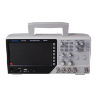
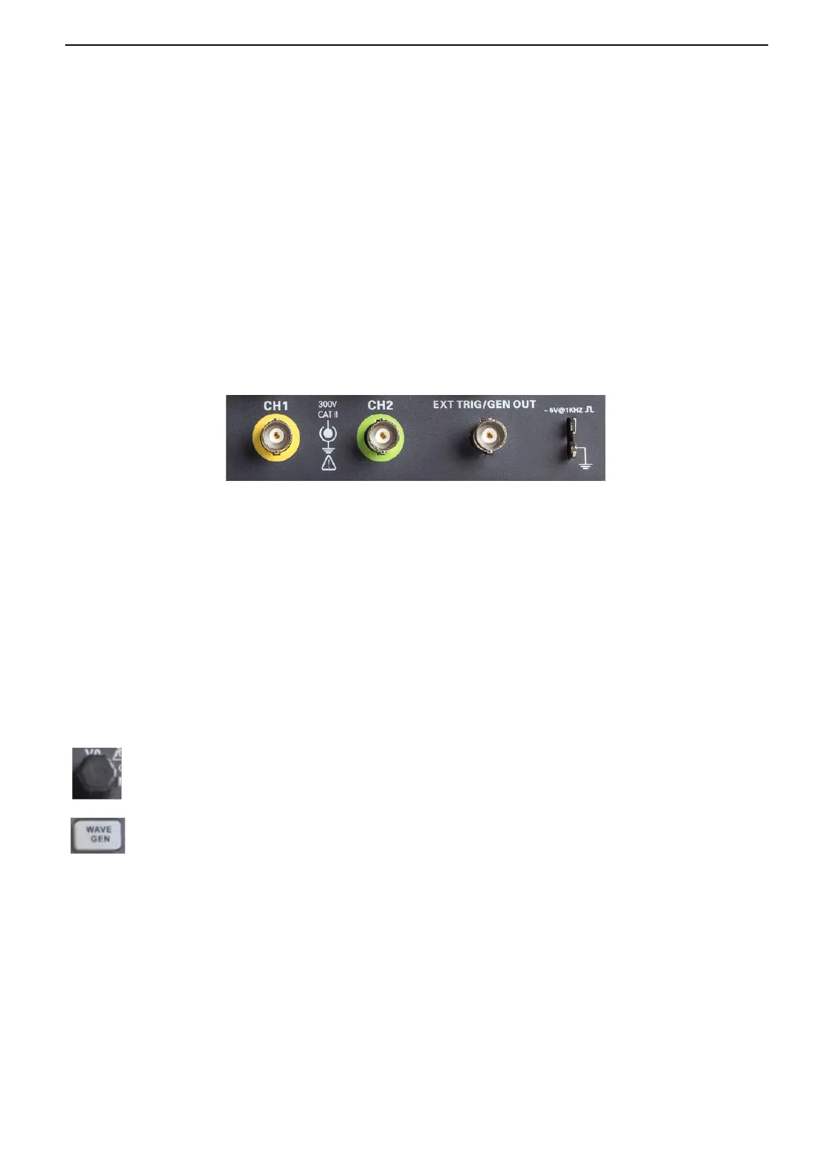
2.2. Connector
◼ CH1, CH2: for an input connector of a measured signal.
◼ EXT TRIG/GEN OUT: Function multiplexing connector, can be used for signal source waveform output
and external trigger signal input. External trigger can trigger on the third channel while collecting data.
Note: GEN OUT function only valid for model with built in function generator.
◼ Probe compensation: The probe compensation signal is output and grounded so that the probe is
matched with the channels of the oscilloscope.
2.3. Multi-function Knobs and Softkeys
V0: Multifunctional knob. Under different menu items (specifically see the operation of each menu), support menu
item selection, cursor movement, level movement; press the knob to select menu, data reset (trigger holdoff time),
And rotate to change the data bit, etc., the operation is extremely convenient.
Wave Gen: To open signal source function (only valid for model with function generator).