72
GB 14 08 04
Maintenance
VV
VV
V
enting the hyenting the hy
enting the hyenting the hy
enting the hy
drdr
drdr
dr
aulic damping syaulic damping sy
aulic damping syaulic damping sy
aulic damping sy
stemstem
stemstem
stem
(SELF TRA(SELF TRA
(SELF TRA(SELF TRA
(SELF TRA
CK only)CK only)
CK only)CK only)
CK only)
The following venting procedure requires a special
venting kit, HARDI ref. no. 720725.
1. Place the trailer on the support leg so that the yoke
goes free from the tractor and the rams can work
freely.
2. Relieve the pressure in the expansion tank and
remove the hydraulic hose.
NOTE! Plug the hose. If this is neglected, the pressure
gauge may be damaged.
3. Fit the two test hoses in the pressure gauge outlets on
the rams (at the rear of the track system).
4. Move the track system from one side to the other
approx. 10 times (full swing).
5. Loosen the plug very carefully in order to leak the air
out of the system.
6. Fit the hydraulic hose on the expansion tank.
7. Remove the level plug and using the tractor hydrau-
lics, cautiously fill oil in the expansion tank until it
reaches the level plug.
8. Fit the level plug and fill the expansion tank to an air
pressure of 5 bar.
9. Fit the 0-400 bar pressure gauge on the pressure
gauge outlet at the ram. Adjust the excess-pressure
valve to approx. 40 bar.
On flat ground it is possible to work with a lower opening
pressure. This gives a more sensible reaction but it also
results in the fact that the trailer can swing when driving
on hilly ground and when swinging at high speed.
TRATRA
TRATRA
TRA
CKER damping prCKER damping pr
CKER damping prCKER damping pr
CKER damping pr
essuressur
essuressur
essur
e setting (SELFe setting (SELF
e setting (SELFe setting (SELF
e setting (SELF
TRATRA
TRATRA
TRA
CK only)CK only)
CK only)CK only)
CK only)
The hydraulic pressure relief valves in the TRACKERs
damping system is factory set to open at 40 bar (580
p.s.i.) which is adequate for most conditions.
If the damping seems too soft or too hard, the set-
tings can be adjusted.
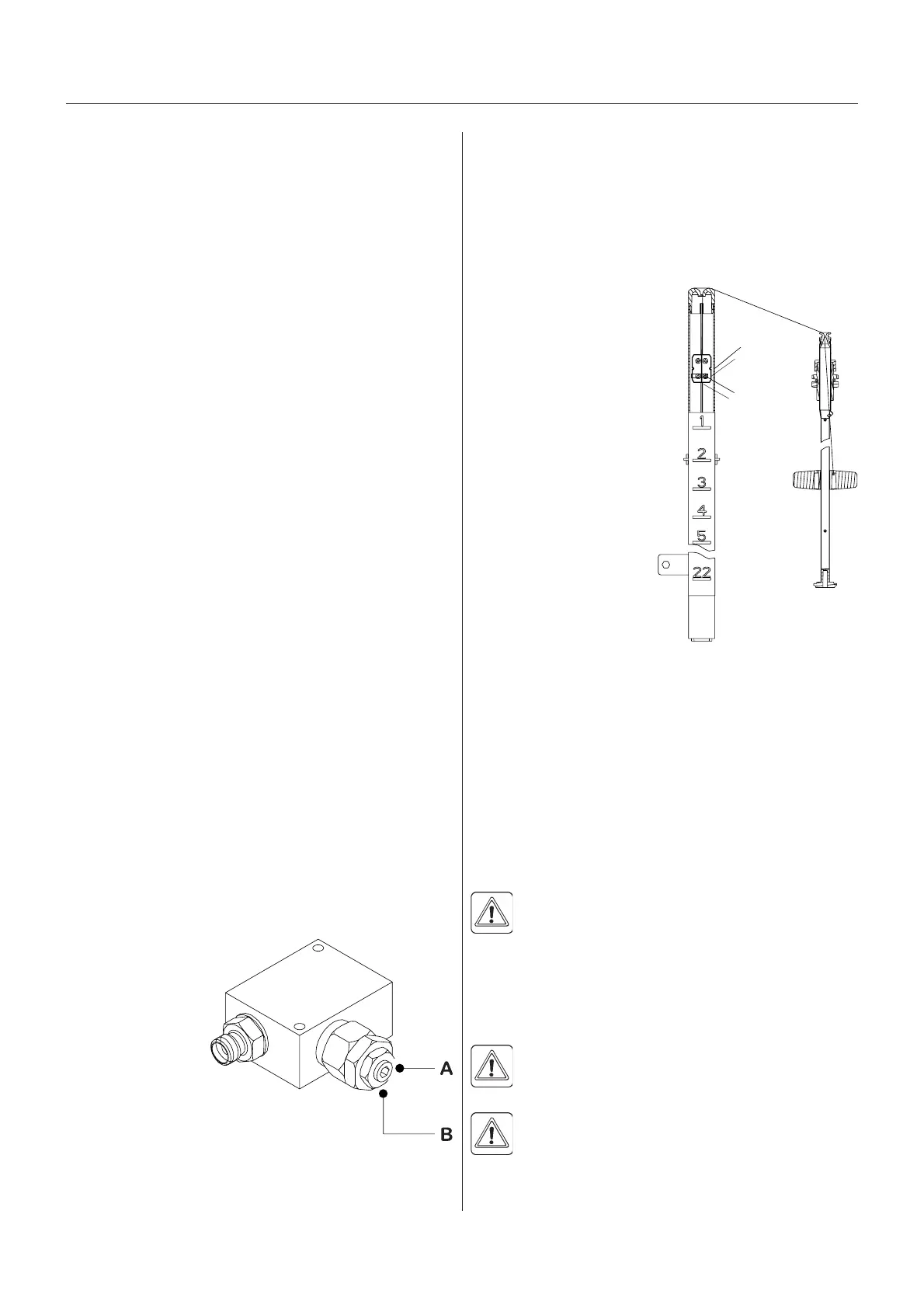
Connect manometers
to the Minimesh
couplings and
control if pressure
is equal for both
sides.
A= Adjusting screw
B= Self-locking nut
NOTE! Too low pressure will result in a swaying trailer.
Too high pressure will influence on the ability to turn with
the tractor.
ShocShoc
ShocShoc
Shoc
k ak a
k ak a
k a
bsorberbsorber
bsorberbsorber
bsorber
ss
ss
s
If the shock absorbers loose their efficiency or start
leaking oil, they should be replaced.
LeLe
LeLe
Le
vv
vv
v
el indicael indica
el indicael indica
el indica
tor adjustmenttor adjustment
tor adjustmenttor adjustment
tor adjustment
The level indicator reading should be checked regularly.
When the tank is empty,
the float should lie on the
stop pin, of the rod, and
the O-ring on the indicator
should be positioned at the
top position line A.
If any deviation is found,
pull out the plug B, loosen
screws C, and adjust the
length of the cord.
CorCor
CorCor
Cor
d rd r
d rd r
d r
eneene
eneene
ene
ww
ww
w
al, leal, le
al, leal, le
al, le
vv
vv
v
el indicael indica
el indicael indica
el indica
tortor
tortor
tor
If the cord on the level indicator has to be changed, the
float guide pole is removed:
1. Remove the tank drain valve (see paragraph Main
tank drain valve) and loosen the fitting holding the
pole in position.
2. Pull the pole down through the drain valve hole till it is
free in the top of the tank.
3. The pole can now be taken out of the tank through the
filling hole.
DANGER! Do not attempt to enter the tank - the
float pole can be removed from outside the tank!
Seal rSeal r
Seal rSeal r
Seal r
eneene
eneene
ene
ww
ww
w
al, dral, dr
al, dral, dr
al, dr
ain vain v
ain vain v
ain v
alvalv
alvalv
alv
ee
ee
e
If the main tank drain valve leaks, the seal and seat can
be changed the following way.
DANGER! Do not enter the inside of the tank -
the parts can be changed from underneath the
tank!
WARNING! Use eye / face protection mask when
dismantling the tank drain valve!
1. Make sure the tank is empty and clean.
2. The valve must be closed and the string loose.
A
B
C
T191-0014
T191-0018
 Loading...