22
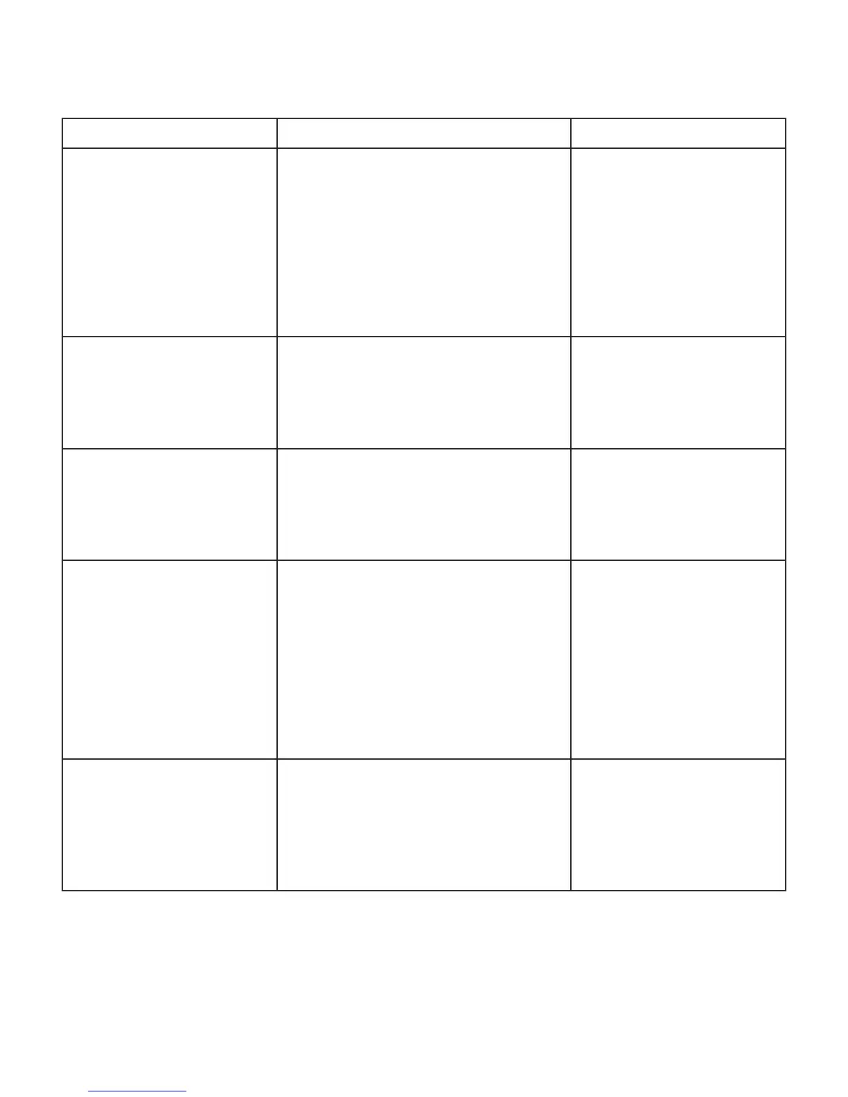
Symptom Cause and Remedy Ref No.
Power On Failure
1. FLT does not light up.
2. STANDBY LED does not light
up.
A) ACCord check.
B) PowerTrans (Main/Standby) check.
C) Fuse’s disconnection check.
D) Connector’s disconnection or disjuction.
Change or close insertion of the connector.
E) Inferior Standby switch.
F) VFD Driver I.C & Resonator check.
1. VFD Driver I.C & Resonator check.
2. VFD Driver clock pulse check.
F (301)
CN301, FPC101
SW(700)
I.C701 SC16315
I.C701 Pin No13
I.C701 Pin No5
Fuse Disconnection. (Power On) A) Inferior transfomer.
B) AMP drive TR out. (POWER TR)
C) AMP drive TR out. (POWER TR)
D) Voltage check.
1. B+(47V)V, B(47)V
Q206(FL, FR, C, SL, SR)
Q205(FL, FR, C, SL, SR)
Key Disorder. A) Key’s being pushed check.
B) Key signal input components inferior.
C) Key PORT check.
D) μCOM I.C inferior
1. μCOM I.C VCC +3.3V check.
I.C101 Pin No. (49, 50, 51)
I.C101 Pin No. (49, 50, 51)
Power Off in 2~3 sec. after Power
On.
A) Regulator I.C out.
1. Signal IN/OUT check.
B) Drive transistor out.(POWER TR)
C) Protection circuit check.
1. Output DC check.
2. μCOM I.C protection terminal check.
D) Connector’s disconnection or disjunction.
E) SLEEP MODE cancellation.
I.C300 (LM1117S_3.3V)
Q205(FL, FR, C, SL, SR)
Q206(FL, FR, C, SL, SR)
μCOM Pin No.(1)
CP(111)
Bump Sound
(During inputselect switch’s
change.)
A) FRONT Mute transistor’s out and inferior.
μCOM front mute control PORT check.
B) CENTER Mute transistor’s out and inferior.
μCOM center mute control PORT check.
C) SURROUND Mute transistor’s out and inferior.
μCOM surround mute control PORT check.
Q(105)
I.C101 Pin No. (28)
Q(107)
I.C101 Pin No. (26)
Q(109)
I.C101 Pin No. (27)
TROUBLESHOOTING
 Loading...