B) DIGITAL INPUT, BASELINE AUDIO PARAMETERS(STEREOSURROUNDMODE)
Measuring methods are based on IHF and IEC standard 268-3
Measurement conditions,unless otherwise noted :
Tone Off or Tone(Bass,Treble), Balance, EQ control : Center Position , Other SW's : OFF, Volume:Max
All Voltage Measurements are made with RMS detector, unless otherwise specified.
R/O = Rated Output, which is 50 W into 8 ohm resistive load, for PCM Digital inputs.
All measurements are made in Stereo mode, at FL and FR Speaker Output jacks, unless otherwise noted.
Power supply : 120 V , 60 Hz
UNIT
}
Rated Stereo Power Output
Rated 6 CH DIRECT Power Output
8ohm,+/- 1%,
Non-Inductive,
455 W
Digital Input data is a 44.1 KHz sampling rate, 16 bit, no Pre-emphasis, PCM bitstream.
No DESCRIPTION INPUT UNIT LIMIT NOMINAL
Gain Difference between
Analog and Digital Input
With a 0 dBFS, 1 KHz PCM bitstream, and Main Volume at 20 dB
below Max, the Output Voltage at FL and FR speaker outputs
should bethe sameas when,applyinga 2 Volt, 1 KHz sinewave
amplitude into an analog Stereo Input. Read the dB difference
between
With a 0 dBFS, 1 KHz sinewave PCM bitstream,and Main Volume
at 20 dB belowMax, set meter to read THD+N Ampl, with dBr
units. Use 'A Weighting' filter, 10 Hz-80 KHz BW. Record the
Output Voltage at FL and FR speaker outputs to be the 0 dBr
Reference val
With Digital Generator amplitude at -999 dBFS (Generator turned
off), 1 KHz sinewavePCM bitstream, and Main Volumeat 20 dB
belowMax, set meter to read Amplitude,10 Hz-22 KHz BW. Take
Amplitude readings on both FL and FR Speaker Outputs.
With a 0 dBFS, 1 KHz sinewave PCM
bitstream, andMain Volumeat 20 dB below
Max, set meter to read THD+N , with % units.
Use 10 Hz-80 KHz BW. Read THD+N Ratio,
with dBr units on both FL and FR Speaker
Outputs. IHF-AFILTER
FRONT "L" AND "R" SPEAKERS
SURROUND "L" AND "R" SPEAKERS
MULTICHANNEL AVAILABLE SPEAKER MODES
FRONT "L" AND "R" SPEAKERS
STEREO MODE AVAILABLE SPEAKER SETTINGS
Both FL andFR Speaker amplifiers driven and loaded with Rated
Resistive Load.
All seven(FL,FR,C,SL,SR ,SBL,SBR ) Speaker amplifiers driven and
loaded with Rated Resistive Load Impedance.
Resistive loads to be connected to Speaker Outputs using a 12 AWG
StrandedSpeaker Wire pair for eachload resistor. Wire length
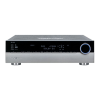
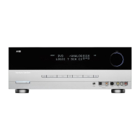
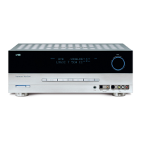
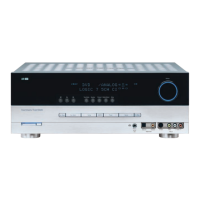
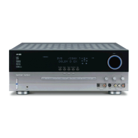
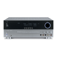
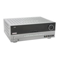
DPR1001 harman/kardon
DETAILED SPECIFICATIONS (CONT'D)
 Loading...