HIGHLANDER II VERTICAL PLATFORM LIFTS: Install Manual
17FEB2021 | 630-00113 REV C
12
INSTALLATION
HIGHLANDER II: SECTION 4
SECTION 4
INSTALL ATION
NO HOISTWAY / NO FLOOR
PENETRATION
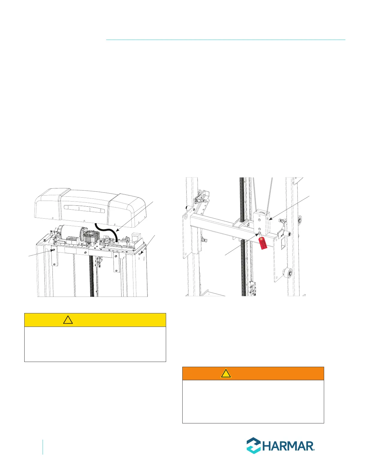
1. Remove 5X front screws.
2. Remove the top cap by loosening the four (4)
side screws and lifting the top cap partially,
then disconnect the cable for status indicator
lights from the control board. See Figure 4-1.
5X front
screws
4X side
screws
Status
indicator
cable
Figure 4-1
3. Remove the front panel by rotating it out
slightly and lifting it out of the lower slots.
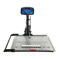
4. Position the VPL tower close to the upper
landing and stand it up using appropriate
material handling processes.
NOTE: Tower frame should only be lifted by the
rectangular tubes below the top plate.
ELECTRICAL CONNECTION
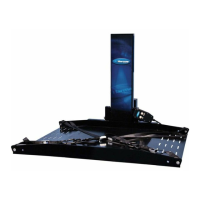
1. Remove and discard the temporary bolt and
pulley to the carriage for shipping. This bolt is
indicated with a red tag. Suspend the pulley
assembly behind the carriage. See Figure 4-2.
Pulley
Assembly
Temporary
Shipping Bolt
Figure 4-2
NOTE: Be sure that the pulley assembly is suspended with
the sheeve at the top and that it is clear to move through
the lift range.
2. Connect the 8-pin platform control box
connector.
WARNING
!
CAUTION
!