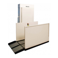
HIGHLANDER II VERTICAL PLATFORM LIFTS: Install Manual
17FEB2021 | 630-00113 REV C
16
INSTALLATION
HIGHLANDER II: SECTION 4
INSTALLING THE TOP
LANDING GATE
WARNING
!
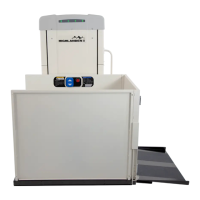
1. Landing wires are pre-wired to the control
board. Retrieve wires that are coiled up inside
the tower and determine routing of wires
going to the landing gate or call send box.
See Figure 4-9 for wiring to a call staon.
See Figure 4-10 for wiring to a landing gate.
See Figure 4-11 for wiring to a call staon and
strike.
Figure 4-9
Figure 4-10
Figure 4-11
NOTE: If the call send switch is installed in the gate, the
wires are routed between the gate and to the top of the
tower. If the call send is located outside the gate, the
wires are routed from the gate to the call send box and
then from the box to the top of the tower.
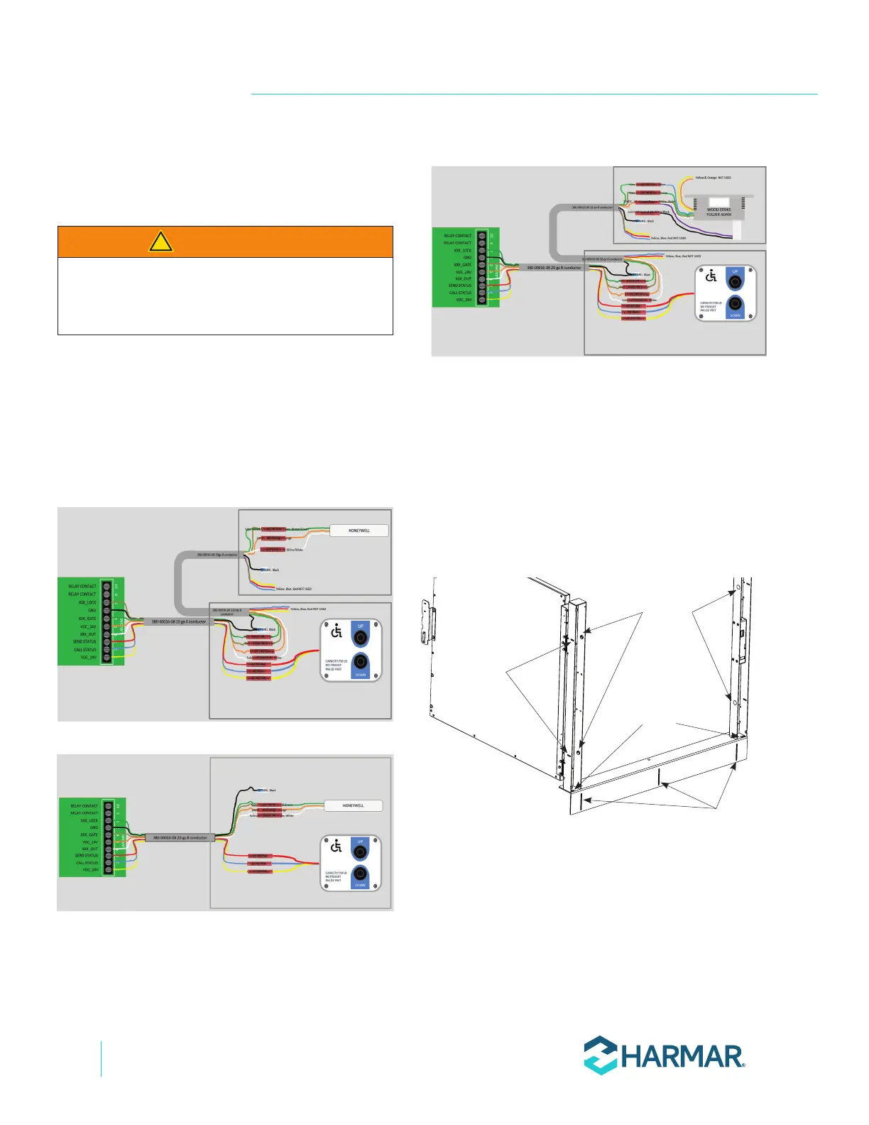
2. Create the necessary space below the gate sill
so the wire can be routed into the gate post
through the wire routing slot. See Figure 4-12.
Post slots
Hole
plugs
Wire routing
slots
Sill
mounting
slots
Figure 4-12
3. Remove small screws and post cover on the
latch side of the landing gate with a No. 1
Phillips screwdriver.