511018854 12/2015 V01
3.3.6 Output Bearing
CHA series AC hollow shaft Servo Actuators incorporate a high stiness cross roller bearing to support output loads. This
specially developed bearing can withstand high axial and radial forces as well as high tilting moments. The reduction gear
is thus protected from external loads, so guaranteeing a long life and consistent performance. The integration of an output
bearing also serves to reduce subsequent design and production costs, by removing the need for an additional output bearing
in many applications. Furthermore, installation and assembly of the CHA servo actuators are greatly simplified.
1)
C=Cross roller bearing, F = Four point contact bearing
2)
These values are valid for moving gears. They are not based on the equation
for lifetime of the output bearing but on the maximum allowable deflection
of the Harmonic Drive® component set. The values indicated in the table must
not be exceeded even if the lifetime equation of the bearing permits higher values.
3)
These values are valid for gears at a standstill and for a static load safety factor f
s
= 1,8 for size 14 ... 20
and f
s
= 1,5 for size 25 ... 58.
4)
These data are valid for n = 15 rpm and L
10
= 15000h
3)4)
These data are only valid if the following conditions are fulfilled:
for M
0
: F
a
=0 N; F
r
=0 N
F
a
: M=0 Nm; F
r
=0 N
F
r
: M=0 Nm; F
a
=0 N
5)
Average value
Technical Data
Tolerances
Table 51.1
Table 51.3
Symbol [Unit] CHA-14A CHA-17A CHA-20A CHA-25A CHA-32A CHA-40A CHA-50A CHA-58A
Bearing type
1)
F F F C C C C C
Pitch circle diameter d
p
[mm] 0.049 0.058 0.070 0.088 0.114 0.134 0.171 0.192
Oset R [mm] 0.014 0.014 0.016 0.018 0.020 0.026 0.028 0.029
Dynamic load rating C [N] 8500 11500 24200 30000 34500 43300 81600 87400
Stating load rating C
0
[N] 11400 17100 31000 45000 59000 81600 149000 171000
Dynamic tilting moment
2)
M
dyn (max)
[Nm] 73 114 172 254 578 886 1558 2222
Static tilting moment
3)
M
0 (max)
[Nm] 155 276 603 1050 2242 3645 8493 10944
Tilting moment stiness
5)
K
B
[Nm/arcmin] 23 40 70 114 350 522 1020 1550
Dynamic axial load
4)
F
A dyn (max)
[N] 2880 4600 15800 19200 22300 42000 56100 57700
Dynamic radial load
4)
F
R dyn (max)
[N] 1450 2300 8600 12700 14600 27500 37300 38400
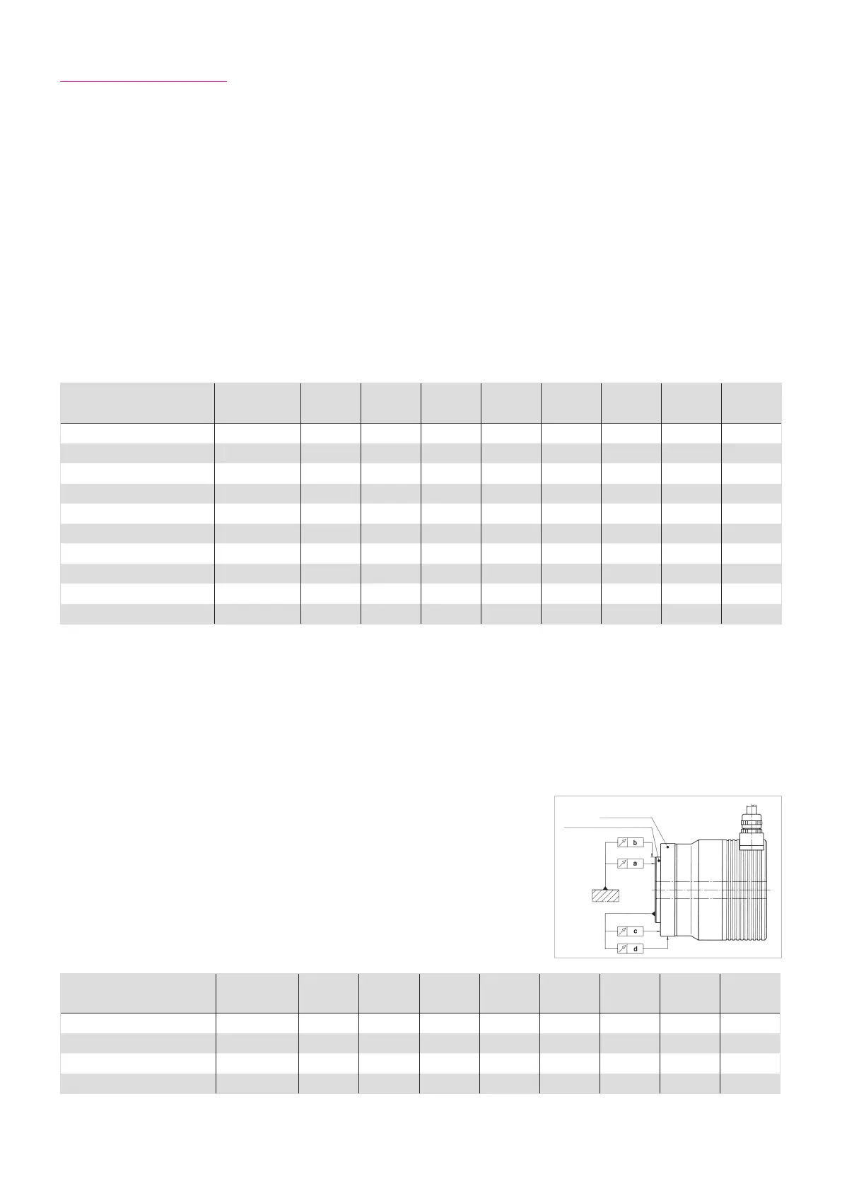
Symbol [Unit] CHA-14A CHA-17A CHA-20A CHA-25A CHA-32A CHA-40A CHA-50A CHA-58A
a [mm] 0.010 0.010 0.010 0.010 0.012 0.012 0.015 0.015
b [mm] 0.010 0.010 0.010 0.010 0.010 0.010 0.010 0.010
c [mm] 0.010 0.010 0.010 0.010 0.012 0.012 0.015 0.015
d [mm] 0.010 0.010 0.010 0.010 0.010 0.010 0.010 0.010
Illustration 51.2
Gehäuse
Abtriebsflansch