74 1018854 12/2015 V01
5.5 Commissioning
Commissioning must be executed in accordance with the documentation of Harmonic Drive AG.
Before commissioning, please check that:
• The actuator is properly mounted,
• All electrical connections and mechanical connections are designed according to requirements,
• The protective earth is properly connected,
• All attachments (brakes, etc) are operational,
• Appropriate measures have been taken to prevent contact with moving and live parts,
• The maximum speed nmax is specified and cannot be exceeded,
• The set up of the drive parameters has been executed,
• The commutation is adjusted correctly.
Check the direction of rotation of the load uncoupled.
In the event of changes in the normal operating behaviour, such as increased temperature, noise or vibration, switch the actu-
ator o. Determine the cause of the problem and contact the manufacturer if necessary. Even if the actuator is only on test,
do not put safety equipment out of operation.
This list may not be complete. Other checks may also be necessary.
Due to heat generation from the actuator itself, tests outside the final mounting position should be limited to 5 minutes of
continuous running at a motor speed of less than 1000 rpm.
These values should not be exceeded in order to avoid thermal damage to the actuator.
5.6 Overload Protection
Temperature sensors are integrated into the servo actuators
and motors to protect them from.
To protect the servo actuators and motors from temperature
overload sensors are integrated into the motor windings. The
temperature sensors alone do not guarantee motor protec-
tion. Protection against overload of the motor winding is
only possible only with an input speed > 0. For special appli-
cations (eg load at standstill or very low speed) is an additio-
nal overload protection by limiting the overload period.
The built specification of the integrated temperature sensors
can be found in the technical data.
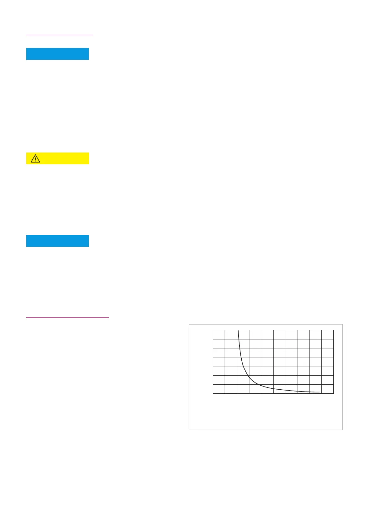
In addition, it is recommended to protect the motor winding
against overload by the use of I²t monitoring integrated in the controller. The graph shows an example of the overload charac-
teristic for the I²t monitoring. The overload factor is the ratio between the actual RMS current and continuous stall current.
ADVICE
70,00
60,00
50,00
40,00
30,00
20,00
10,00
0,00
0,00 0,50 1,00 1,50 2,00 2,50 3,00 3,50 4,00 4,50 5,00
time [s]
I / Is
Over load characteristic
Illustration 74.1
l
s
= Continuous stall current
l = Actual effective current (l ≤ l
max
)
NOTE
ATTENTION