vi
RF-5800H 150-WATT COMMUNICATION SYSTEM
TABLE OF CONTENTS
LIST OF FIGURES
Figure Page
1-1 RF-5800H 150-Watt Communication System
1-2 Maintenance Flow Chart . . . . . . . . . . . . . . . . . . . . . . . . . . . . . . . . . . . . . . . . 1-3
1-3 Relationship of Units in RF-5800H 150-Watt Vehicular System. . . . . . . . . . . 1-5
1-4 RF-5800H-V001 150-Watt Vehicular System Family Tree. . . . . . . . . . . . . . . 1-7
1-5 RF-5800H-V002 150-Watt Vehicular System with Pre/Postselector and
Lowpass Filter Family Tree . . . . . . . . . . . . . . . . . . . . . . . . . . . . . . . . . . . 1-9
1-6 Relationship of Units in RF-5800H 150-Watt Base Station Systems . . . . . . . 1-11
1-7 RF-5800H 150-Watt Base Station System Family Tree . . . . . . . . . . . . . . . . . 1-13
1-8 RF-5800H 150-Watt Base Station System with Pre/Postselector
Family Tree . . . . . . . . . . . . . . . . . . . . . . . . . . . . . . . . . . . . . . . . . . . . . . . 1-15
1-9 Relationship of Units in RF-5800H 150-Watt Mini Transit Case System . . . . 1-18
1-10 RF-5800H 150-Watt Transit Case System Family Tree . . . . . . . . . . . . . . . . . 1-19
1-11 RF-5800H 150-Watt Transit Case System with Pre/Postselector and
Lowpass Filter Family Tree . . . . . . . . . . . . . . . . . . . . . . . . . . . . . . . . . . . 1-21
1-12 150-Watt System with Locking Devices Installed. . . . . . . . . . . . . . . . . . . . . . 1-24
2-1 RF-5800H 150-Watt Vehicular System Installation and Maintenance
Clearances (-V001 Configuration) . . . . . . . . . . . . . . . . . . . . . . . . . . . . . . 2-7
2-2 RF-5800H 150-Watt Vehicular System Installation and Maintenance
Clearances (-V002 Configuration) . . . . . . . . . . . . . . . . . . . . . . . . . . . . . . 2-9
2-3 RF-5800H 150-Watt Base Station System Installation and Maintenance
Clearances . . . . . . . . . . . . . . . . . . . . . . . . . . . . . . . . . . . . . . . . . . . . . . . . 2-11
2-4 RF-5800H 150-Watt Transit Case System Installation and Maintenance
Clearances . . . . . . . . . . . . . . . . . . . . . . . . . . . . . . . . . . . . . . . . . . . . . . . . 2-12
2-5 RF-5073VSM Shock Mount Dimensions . . . . . . . . . . . . . . . . . . . . . . . . . . . . 2-13
2-6 RF-5800H 150-Watt Vehicular System and Transit Case System Installation
Configurations . . . . . . . . . . . . . . . . . . . . . . . . . . . . . . . . . . . . . . . . . . . . . 2-15
2-7 RF-5800H 150-Watt Base Station System Installation Configuration . . . . . . 2-17
2-8 RF-5800H 150-Watt Vehicular System Cable Interconnects
(-V001 Configuration). . . . . . . . . . . . . . . . . . . . . . . . . . . . . . . . . . . . . . . . 2-19
2-9 RF-5800H 150-Watt Vehicular System Cable Interconnects
(-V002 Configuration). . . . . . . . . . . . . . . . . . . . . . . . . . . . . . . . . . . . . . . . 2-20
2-10 RF-5800H 150-Watt Base Station and Transit Case System (-B001 and -
TM001) Cable Interconnects . . . . . . . . . . . . . . . . . . . . . . . . . . . . . . . . . . 2-21
2-11 RF-5800H 150-Watt Base Station and Transit Case System
(-B002 and -TM002) Cable Interconnects . . . . . . . . . . . . . . . . . . . . . . . . 2-22
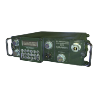
3-1 RF-5833H-PA Front Panel Controls and Indicators . . . . . . . . . . . . . . . . . . . . 3-1
4-1 RF-5800H 150-Watt Vehicular System RF, Audio, and Control Paths. . . . . . 4-2
4-2 RF-5800H 150-Watt Vehicular System Power Distribution Diagram . . . . . . . 4-5
4-3 RF-5800H 150-Watt Base Station System Power Distribution Diagram . . . . 4-7
6-1 Troubleshooting Process Used in this Chapter . . . . . . . . . . . . . . . . . . . . . . . 6-2
6-2 Sample Fault Code Display . . . . . . . . . . . . . . . . . . . . . . . . . . . . . . . . . . . . . . 6-7
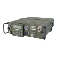
7-1 RF-5833H-PA 150-Watt Power Amplifier . . . . . . . . . . . . . . . . . . . . . . . . . . . . 7-5
7-2 25 MHz Lowpass Filter Kit . . . . . . . . . . . . . . . . . . . . . . . . . . . . . . . . . . . . . . . 7-6
7-3 RF-5071VSM Shock Mount Assembly. . . . . . . . . . . . . . . . . . . . . . . . . . . . . . 7-7
7-4 RF-5073VSM Shock Mount Assembly. . . . . . . . . . . . . . . . . . . . . . . . . . . . . . 7-8
 Loading...