12
Form No. 3CSFRM-0118
English
INSTALLATION
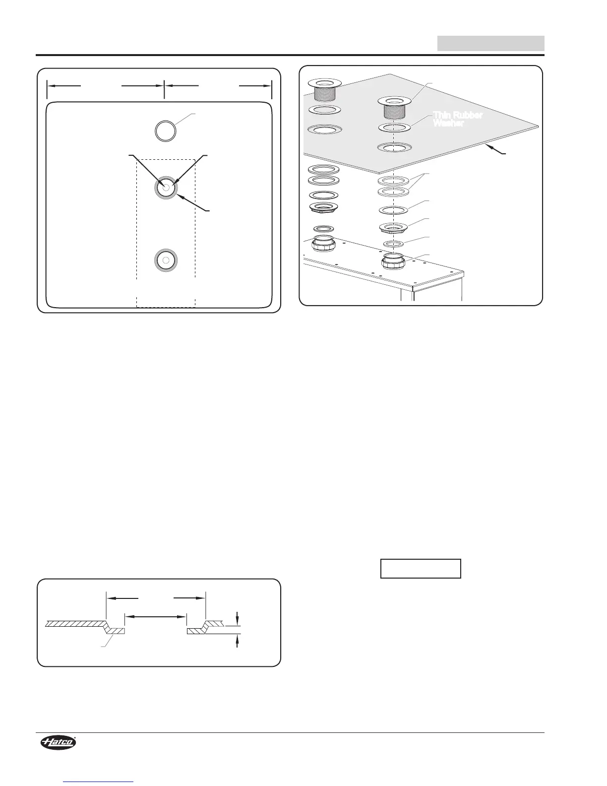
3/4" (19 mm)
Pilot Hole
2" (51 mm)
Diameter Hole
Front edge of heater should be flush to the
front of the sink or holding vessel.
3'
(914 mm)
MAX
3'
(914 mm)
MAX
3" (76 mm)
Diameter
Offset
Holding Vessel
Drain
Top View of Sink or Holding Vessel
NOTE: The dotted lines in the image above indicate the
position of the unit under the sink or holding vessel.
1. Locate the template on the bottom of the sink or holding
vessel.
• The template should be positioned exactly above where
the water heater will be positioned below the sink or
holding vessel.
• Make sure the front edge of the template is flush with the
front edge of the sink or holding vessel.
• FR Models should be positioned with no more than 3′
(914 mm) on either side when mounted under the sink
or holding vessel.
2. Center punch and drill a 3/4″ (19 mm) pilot hole at each of
the two center marks on the template.
NOTE: The pilot holes are for cutting larger holes with a
knockout hole punch.
3. Remove the template and cut a 2″ (51 mm) diameter hole
at each pilot hole location using a knockout hole punch.
4. Make a 1/8″ (3 mm) offset around each 2″ (51 mm)
diameter hole. The offset should be a diameter of 3″ (76
mm) centered around the hole.
2"
(51 mm)
Dia. Hole
3"
(76 mm)
Dia. Offset
1/8"
(3 mm)
Offset
Height
Sink or Tank
Bottom
Side View of Hole and Offset
Thin Rubber
Washer
Drain Spud
Sink/
Vessel
Bottom
Two Thick
Rubber Washers
Fiber Washer
Locknut
Union Washer
Union Nut
Installing the Drain Spud Assembly
5. Unscrew the drain spud assembly from the welded pipe on
the heater.
6. Unscrew the locknut from the drain spud assembly and
slide off all of the washers except the thin rubber washer.
7. With only the thin rubber washer attached to the drain
spud, slide the drain spud through the sink hole from
above.
8. Secure the drain spud assembly to the sink or holding
vessel.
a. From under the sink, slide the two thick rubber washers
followed by the fiber washer onto the drain spud.
b. Screw the locknut (flat side up) onto the drain spud.
9. Repeat steps 5–8 for the other spud assembly.
10. Secure the unit to the sink or holding vessel. Two people
may be required for this step.
a. Position the unit under the two spud assemblies.
NOTE: Make sure the union washers are positioned properly
inside the union nuts and are not crimped.
b. Screw the union nut to the threaded drain spud assembly.
NOTICE
Do not use excessive force when tightening unions or nuts.
Over-tightening and excessive force may cause leaks.
11. Tighten the union nuts and locknuts securely.
12. Verify drain valve handle is in closed (vertical) position.
13. Fill the sink or holding vessel with water and check for
leaks.
NOTE: A 3/4″ (19 mm) hose or pipe may be connected to the
sump drain and run to an open site drain. The sump
drain should not be permanently connected to the
sanitary drain system. Check local plumbing code
for proper drain installation. See the MAINTENANCE
section for more information.