10
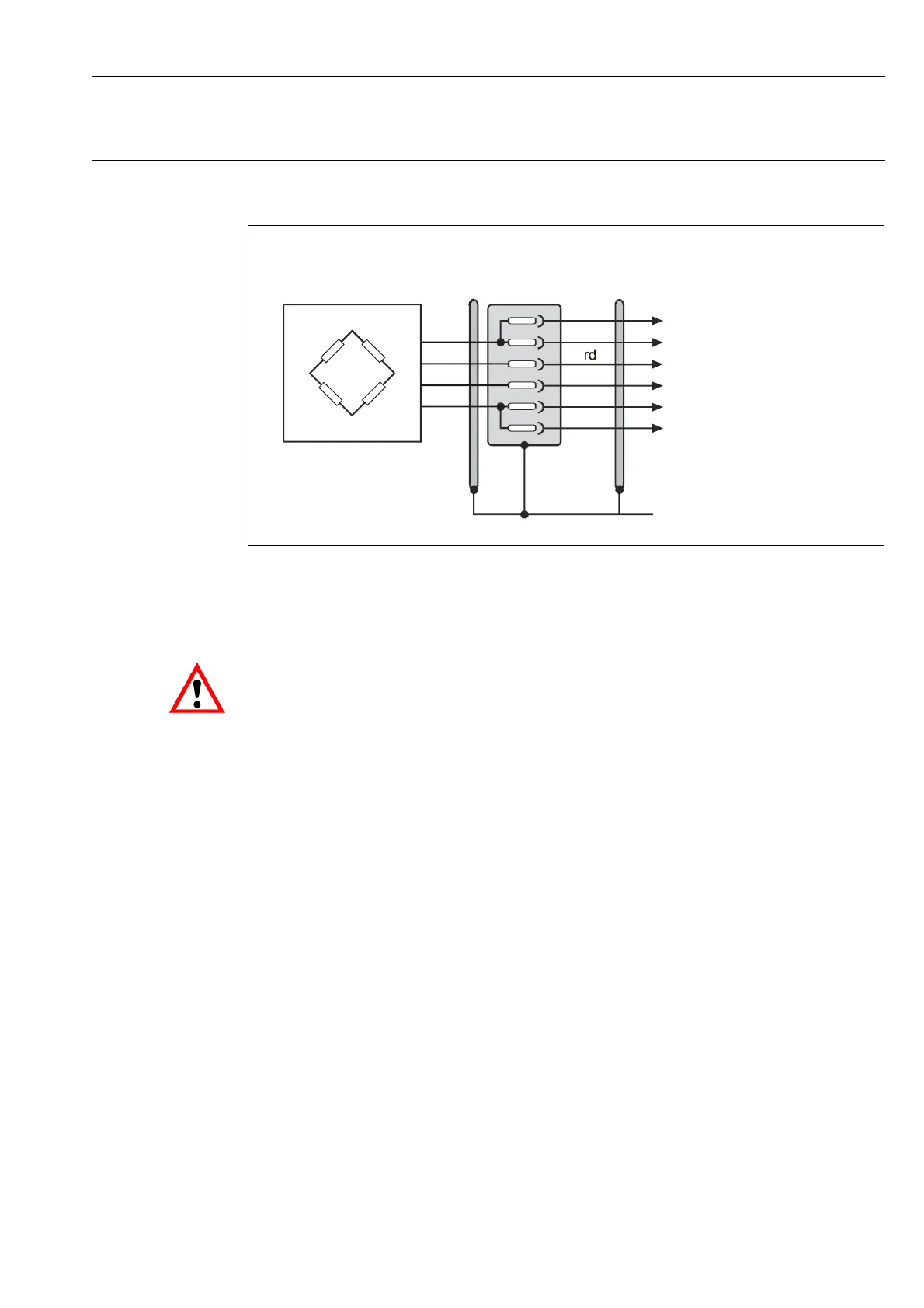
Transducer connection
HBM AED9301B
Plug-in connection
Cable to
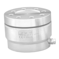
Transducer
bu
rd
wh
bk
bu
gn
wh
gy
bk
Fig. 3.1-3: Transducer connection in 4-wire circuitry via a 6-core cable extension
When connecting several transducers, it is advisable to use an HBM junction box VKKx. In
general, the feed lines running to the AED should be shielded cables.
Notes on type of connection, length and cross-section of cables:
Depending on the bridge resistance of the load cell being used and the length and cross-
section of the load cell connection cable, there may be voltage drops that can reduce the
bridge excitation voltage. The voltage drop at the connection cable is also dependent on tem-
perature (copper resistance). Likewise, the output signal of the load cell changes in propor-
tion to the bridge excitation voltage.
Effect on the measurement result with the internal Auto calibration function:
Auto calibration safeguards the measurement accuracy of the measuring amplifiers (see
“Hardware and Functions” of the AD103C).