Transducer connection
11
AED9301B HBM
6-wire circuit (standard mode of operation):
This will correct all the effects of the load cell cabling up to the feedback points. Even chang-
ing the length of a cable after calibration will not make any difference to the measurement
results.
For load cells with a 6-wire connection, feedback lines 2´ and 3´ are bridged in the load cell
with excitation 2 and 3 (Fig. 3.1-2). For load cells with a 4-wire connection, the feedback
bridges must be implemented directly at the load cell connection (Fig. 3.1-3).
4-wire circuit:
As correction through AUTOCAL can only ever take place up to feedback points 2´, 3´, all
the changes of cable resistances affect the measurement result. This means that even if no
further changes are made to the 4-wire cable used for calibration, there will still be meas-
urement errors when there are temperature changes, because the cable resistance and pos-
sibly the contact resistances at the connectors are temperature-dependent. With the 4-wire
circuit, feedback lines 2´ and 3´ are directly connected at connection terminals 2 and 3 in the
AED (see Fig. 3.1-4).
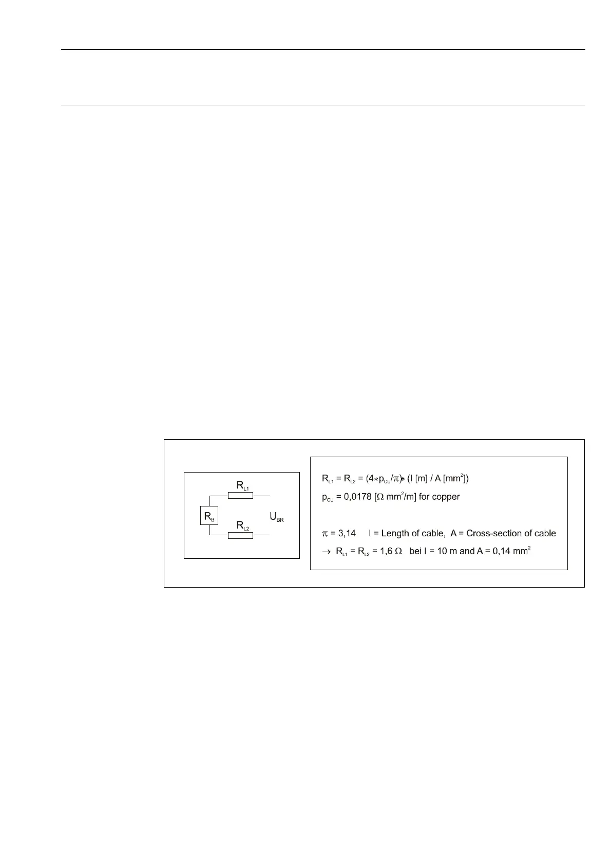
Equivalent circuit of the bridge with bridge resistance R
B
and supply lines with
line resistances R
L1
and R
L2
:
The voltage drop over the bridge feeder cables can be determined from bridge resistance
RB, cable length l, cable cross-section A and the bridge excitation voltage:
U
B
+ U
RL1
+ U
RL2
= U
BR