Connecting digital inputs/outputs
17
AED9301B HBM
control inputs
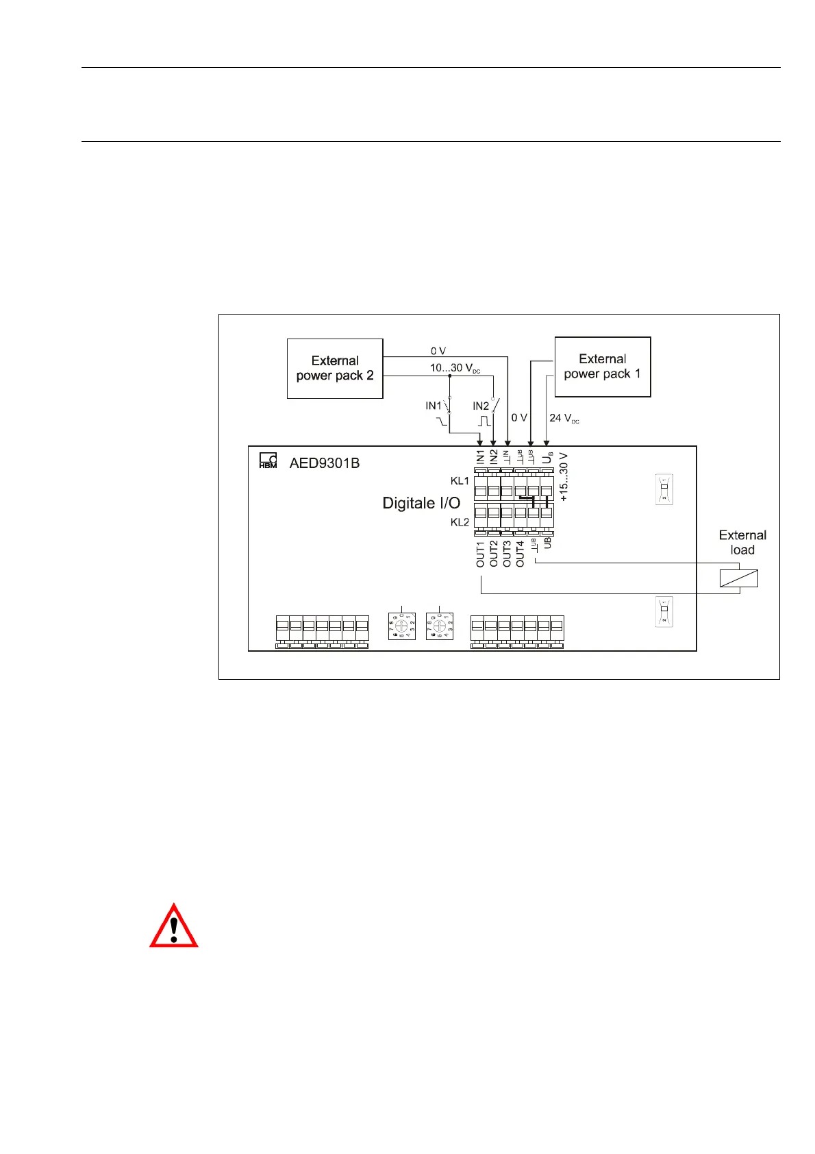
Control inputs IN1 and IN2 are initially electrically isolated from supply voltage U
B
and from
the measuring ground, the reference potential is ground IN at terminal KL1 on the right next
to the inputs.
Fig. 3.4-1: Connection of digital I/Os, inputs and external power pack 1 electrically isolated
Logic level:
IN1: Trigger: quiescent level = low, active edge = high-low edge
Break Dosing: quiescent level = low, activation = low-high-low-Puls
(duration 20 ms)
IN2: Taring or
Start dosing
quiescent level = low, activation = low-high-low-Puls
(duration 20 ms)
Unused inputs remain open. If the input circuit is also supplied via U
B
, the ground of the
inputs and the ground of the U
B
must be connected.