18
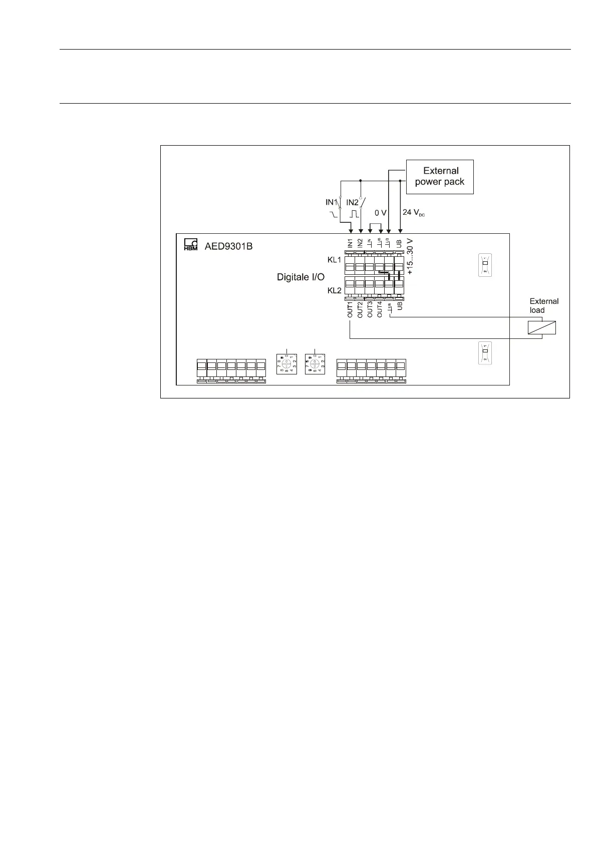
Connecting digital inputs/outputs
HBM AED9301B
Fig. 3.4-2: Connection of digital inputs and outputs, inputs and external power pack not electrically
isolated (IN1 = trigger)
Control outputs:
Digital outputs OUT1…4 are electrically isolated and are supplied via external supply voltage
U
B
. They are implemented as High side switches. Consequently, consumers must be con-
nected to ground. The outputs are short-circuit-proof and can drive ohmic and inductive
loads with currents up to approx. 0.5 A per output.
Logic level: OUT inaktiv
voltage is Low (H-side switches deactivated)
OUT aktiv
voltage is High (H-side switches activated)
The functions of the digital inputs and outputs differ in accordance with the type of measuring
amplifier used (basic, plus)