C9B
14
A2088-3.0 en/de/frHBM
6 Electrical connection
The following can be connected for measurement signal conditioning:
• Carrier‐frequency amplifier
• DC amplifier
designed for strain gage measurement systems.
The C9B force transducer is delivered with a four‐wire configuration.
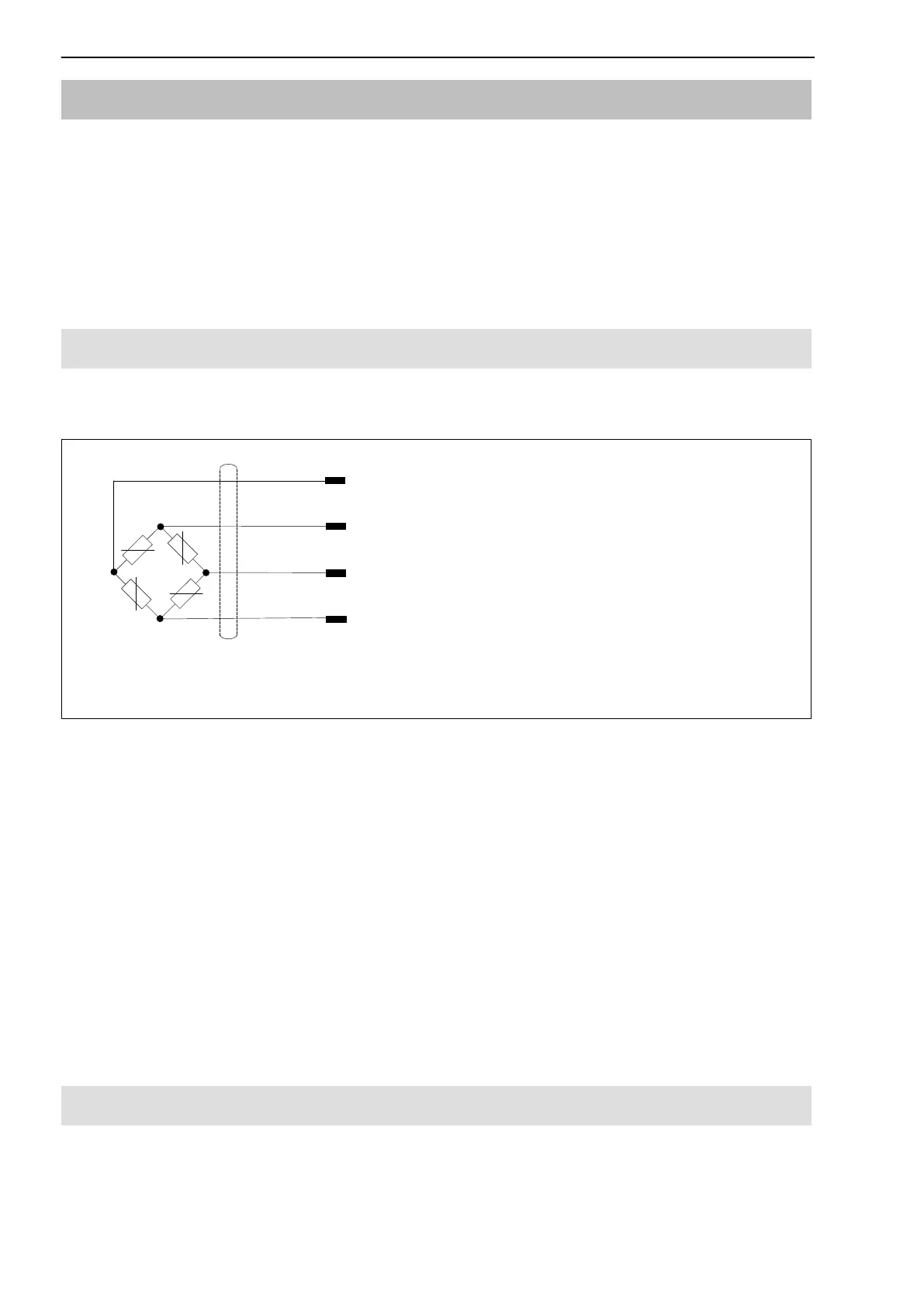
6.1 Connection with four‐wire configuration
The transducer is delivered with a 1.5 m cable with free ends as standard.
1: white Measurement signal (+)
2: black Excitation voltage (-)
4: red Measurement signal (-)
3: blue Excitation voltage (+)
Cable shield, connected
to the housing
Fig 6.1: Transducer with a four‐core connection cable
With this cable assignment, the output voltage at the measuring amplifier is
positive when the transducer is loaded with compressive forces. If a negative
output voltage is required at the amplifier when the transducer is under com
pressive loading, the two measurement signal leads must be transposed.
The connection cable shielding is connected to the transducer housing. Trans
ducers with free cable ends must be fitted with connectors complying with the
EMC guidelines. The shielding must be connected extensively. With other
connection techniques, an EMC‐proof screen should be applied in the wire
area and this screen should also be connected extensively (see also HBM
Greenline Information, brochure i1577).
6.2 Shortening the cable
The cable can be shortened, influence on the temperature coefficients of the
characteristic values or the sensitivity itself is low.