Electrical connection
24 A03729_03_YI0_01 HBM: public C9C
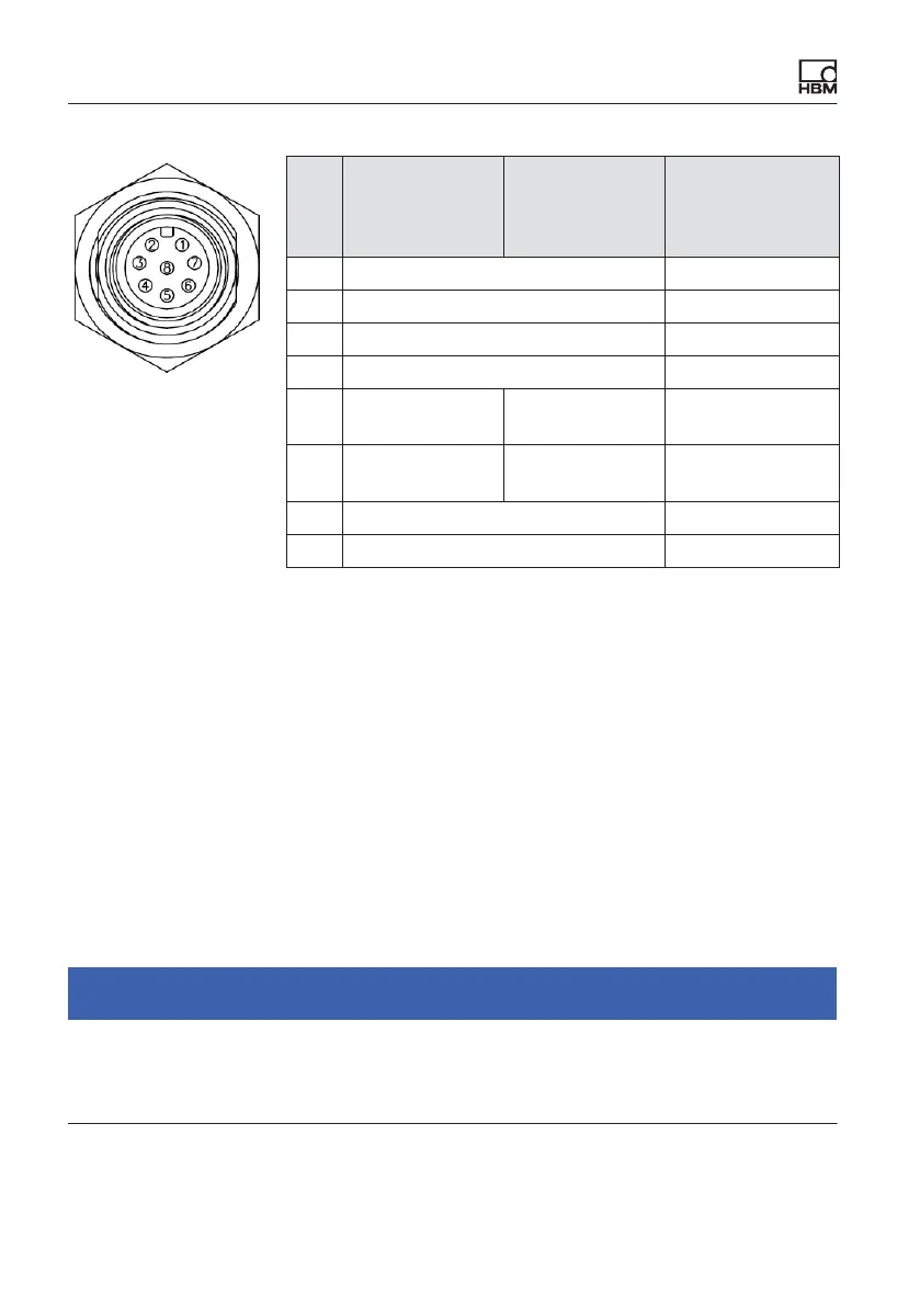
Pin Version VA 1
(voltage out
put)
Version VA 2
(current out
put)
KAB168
connection
cable wire
assignment
1 Supply voltage 0 V (GND) white
2 Not in use brown
3 Control input zero setting green
4 Not in use yellow
5 Output signal
0 ... 10 V
Output signal
4 ... 20 mA
gray
6 Output signal
0 V
Not in use pink
7 Not in use blue
8 Voltage supply +19 ... +30 V red
The cable connecting the inline amplifier to the next link in the measurement
chain must not exceed 30 m in length.
7.2.3 Operating the inline amplifier/zeroing the measurement chain
The measurement starts as soon as the sensor is connected to a supply
voltage and the output of the amplifier is connected to the next link in the
measurement chain.
If you apply a voltage > 10 V to the “Zero” input, a one-time zeroing is
performed. After this zeroing, the device continues to measure, even if you
apply a voltage above 10 V to the input.
To trigger a new zeroing operation, the input must first be set to 0 V and then
be reset by applying a voltage of over 10 V.
Notice
Please note that you can zero the measurement chain with any force applied. If
an initial load is already acting on the force transducer, it is essential to
consider it, otherwise the force transducer may be overloaded.