©HBS Bolzenschweiss-Systeme GmbH & Co. KG
All rights reserved – Reprinting, in whole or in part, only with the approval of the manufacturer
26
9 Welding Process
Drawn-Arc Stud Welding with Ceramic Ferrule
Drawn-arc stud welding with ceramic ferrule is used with welding elements of 3
to 25 mm diameter (preferably above 12 mm diameter) and with welding times of
about 100 to 2 000 ms. It is generally suitable for all welding positions. When stud
welding with ceramic ferrule, the welding position is PA (at position). The major part
of all applications applies to this procedure.
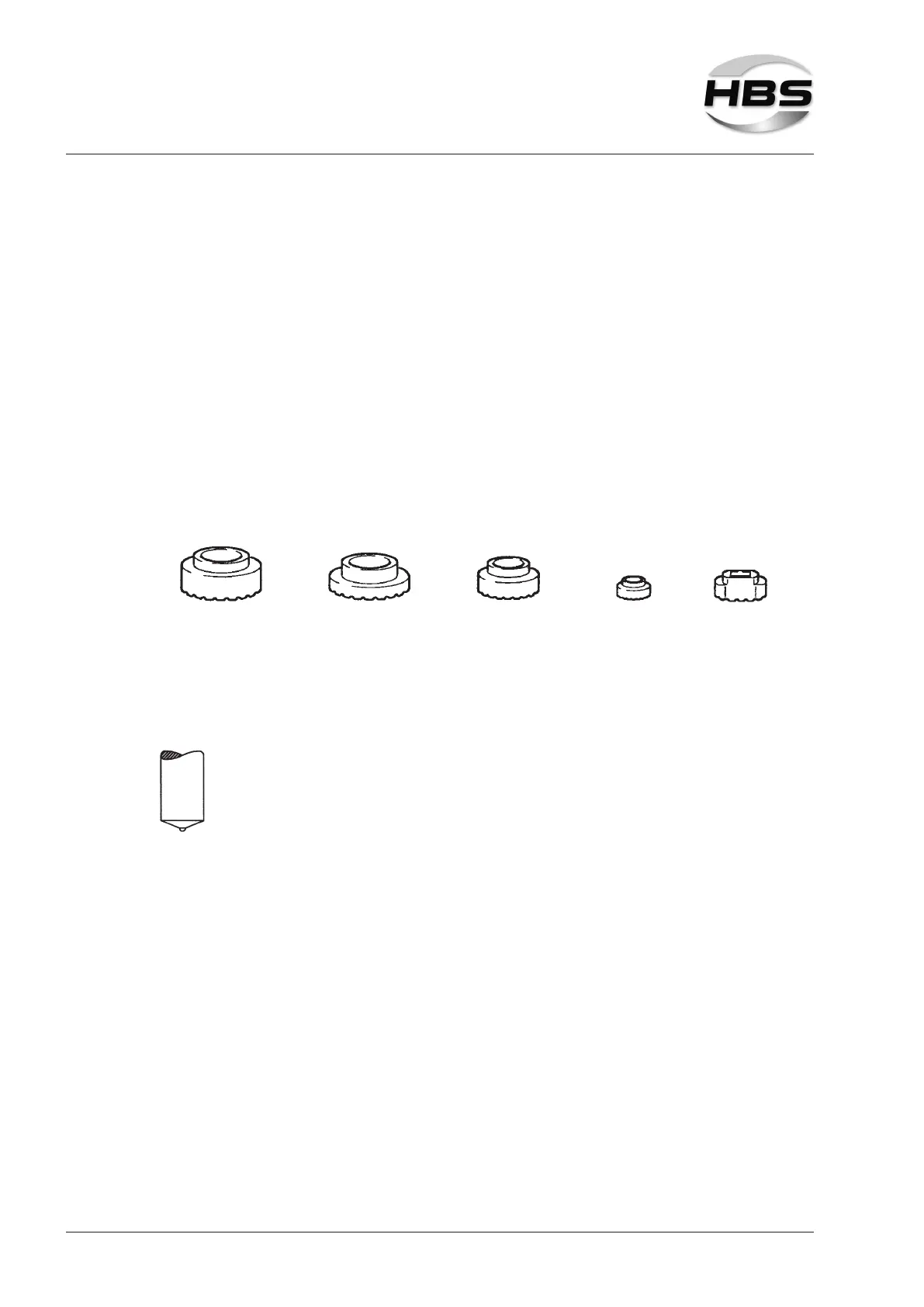
The ceramic ferrule (CF):
– prevents atmosphere from getting to the weld pool by a formation of metal vapor
in the arc chamber
– stabilizes and concentrates the arc, thus decreasing the arc blow effect
– forms the melt under pressure to a weld collar and supports the weld pool on a
vertical wall and overhead
– protects the welder from arc radiation and welding spatters
Normally, the ceramic ferrule is used for only one weld and is removed after solidi-
cation of the weld pool.
Standard welding elements and ceramic ferrules are described in EN ISO 13918.
When using concrete anchors or shear connectors the front area can be plane cons-
tructed with a small pressed-in aluminium ball.
Studs with cone-shaped front area and aluminium ball are preferably
used with ceramic ferrule.
 Loading...