34
- -
--
- -
--
·
Refer to
Pictorial
4-3 (fold-out
from
Page
39)
for the following steps.
Place a
soft
cloth
on
your
work
surface.
In
the following steps
place the amplifier chassis
on
this
cloth
to
protect
it
from
scratches .
. )
Mount
the
wood
side panels to the
left
and
right
side of the
amplifier.
Use
two
No
6 x 5/8"
sheet metal screws in '
each
panel.
(
Mount
the bottom trim panel to the
bottom
of
the
front
panel with
three
No
6 x 1/4" sheet metal screws.
(\')
Push
and
release
each pushbutton to
make
sure they operate
freely.
If
any
pushbuttons should bind in the
bottom trim panel, loosen the
six
screws holding the amplifier
circuit
board
and
move
the
circuit
board
until
the pushbuttons are
free.
Then
retighten
the screws.
(~ )
Take
the
window
and
carefully
wipe
it
clean with a
soft,
dry
cloth.
( , Place the
window
over the control
shafts
on
the
front
panel.
Mount
the top trim panel
on
top of
the
front
panel with three
No
6 x
1/4" sheet metal screws.
Be
sure
to
position
the
window
in the groove
in the bezel .
(
Push
one
knob
onto
each
control
shaft.
PICTORIAL 4-4
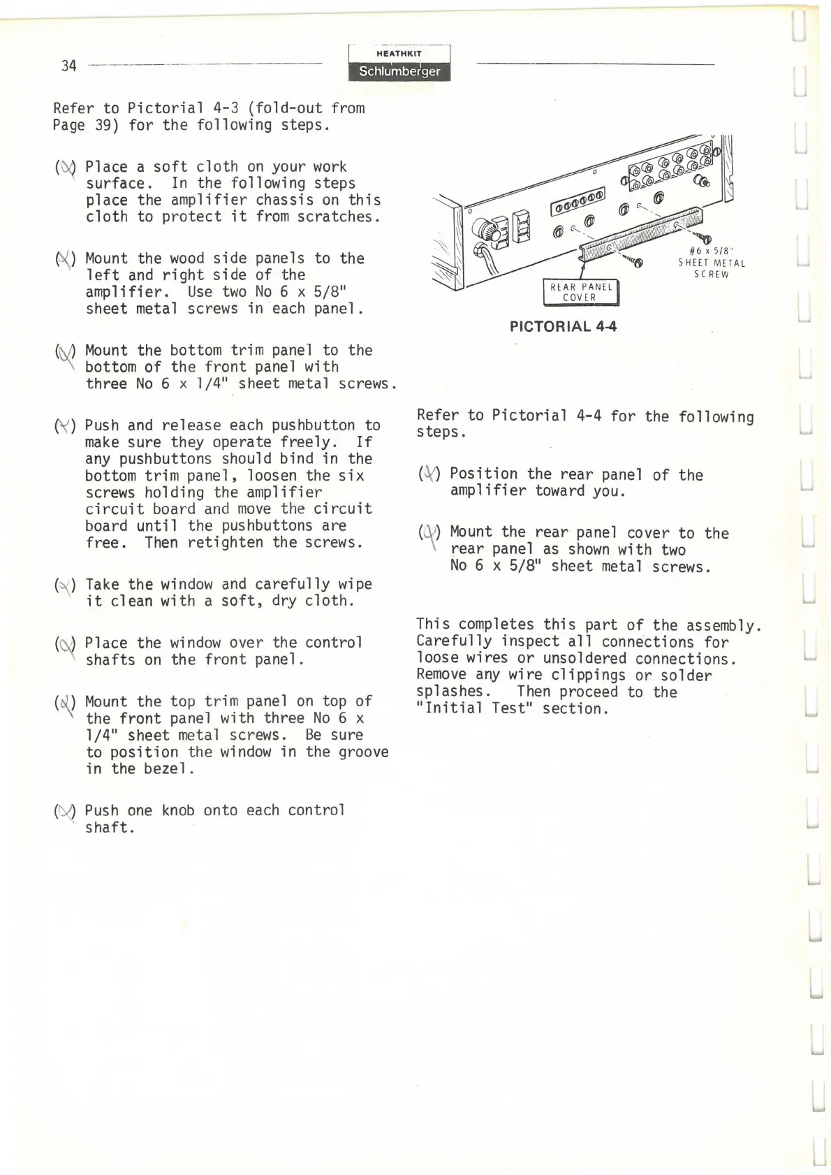
Refer to
Pictorial
4-4
for
the following
steps.
(
Position the rear panel of the
amplifier toward you.
Mount
the
rear
panel cover to the
rear
panel
as
shown
with
two
No
6 x 5/8" sheet metal screws.
This completes
this
part
of
the assembly.
Carefully inspect
all
conne
·
ctions
for
loose wires or unsoldered connections.
Remove
any
wire clippings or
solder
splashes.
Then
proceed to the
"Initial
Test"
section.
w