18 30803 Rev X 08/04
CALIBER DIRECT VENT INSTALLATION INSTRUCTIONS
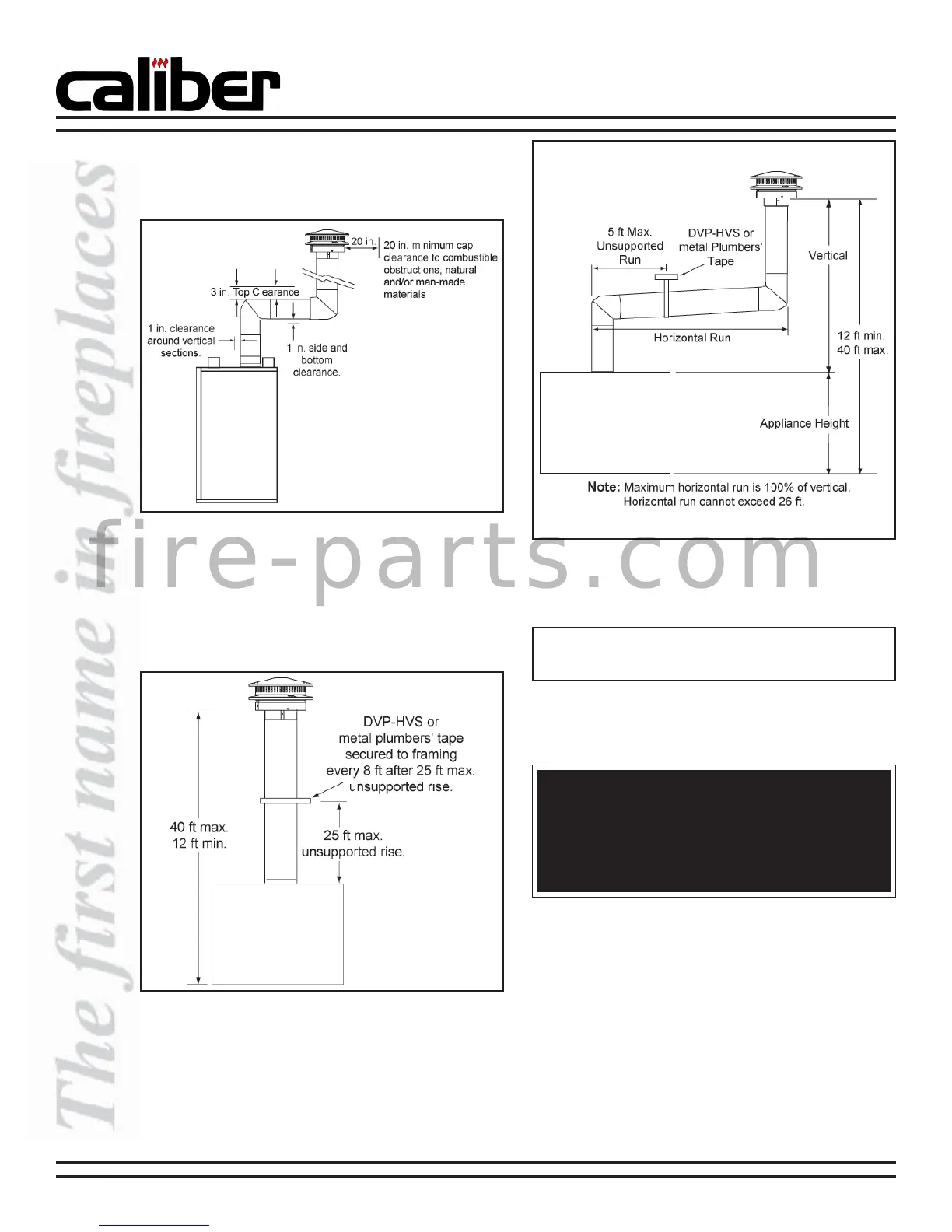
3. Vertical Termination
a. Top and Rear Vent Clearances
See Figure 40 for clearance information.
b. Top Vent Lengths
Various venting configurations are shown in
Figures 41 and 42 from which maximum vent
runs can be determined.
Figure 40
Vertical Termination Clearances
(top vent shown)
Figure 41
Vertical Termination Vent Lengths
Figure 42
Maximum Horizontal Vent Lengths
WARNING!
The horizontal run of vent must have a 1/4 in. rise
for every 1 ft of run towards the termination. Never
allow the vent to run downward. This could cause
high temperatures and may create a fire hazard.
Note: Horizontal runs will require the use of one vent
support (or metal plumber’s strap) for every 5 ft of vent.
f i r e - p a r t s . c o m
 Loading...