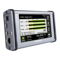
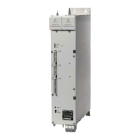
2.1 Specific data for TNC 151 B/TNC 155 B
Control inputs
Potential-free opto-couplers (switched into groups)
Operating voltage
Opto-coupler switched
pax. 30 V -, filtered
= 15v
Opto-coupler open
5 8V
Loading per input 4 IOmA
Control relay outputs
Potential-free relay contact (switched into groups)
Operating voltage
max.30V-/min. 15V-
Operating current per contact max. 50 mA
Permissible load Resistance load;
Inductive load only with quenching
diode parallel to inductivity
To prevent welding of contacts in the event of short circuiting, every contact is provided with a current limiting
resistor of 47 ohms in series.
Caution!
Connect control O-volt for inputs and outputs of control to a common groundin
See tiiring and grounding diagram TNC 151/TNC 155. Operational ground
2.2 Specific dalta for TNC 151 Q/TNC 155 Q
Nominal values and tolerances
External voltage supply for PLC
Nominal voltage: 24 V, -
Voltage range: 20.4 V to 28.8 V
Furthermore, superimposed alternating voltages with a relative oscillation width of 10 % - related to the average
DC-voltage value - are permissible.
Circuitry example:
Definition:
+2&V
g = DC-voltage average: 20.4 _ . . 28.8 V
AU = Oscillation width: -= IO % related to u
k Au
toPLl00B/ll0B
L
u
ov
Binary input signals (EO to E62 and E64 to El261
Nominal voltage: 24 V -,
Voltage range for signal “1”: 16.5 V to 30 V
Voltage range for signal “0”: - 3 V to + 4 V
Current range for signal “1”: 6.2 mA to 12.6 mA
Please note:
Interference signalsL1 ms at the PLC-inputs are filtered with a low pass Schmitt-Trigger-input circuit. Long
duration interference signals must be faded out via software.
6

 Loading...


