6 Inputs and outputs
30 Positioner DC 6-06
6 Inputs and outputs
This section describes the inputs and outputs of the control unit. For inputs/outputs whose
type is configured, please refer to the chapters indicated.
The terminal for the particular signal is underscored and shown in bold print.
6.1 Switch functions via digital inputs
One fixed digital input is available. The system automatically configures a second input as
a digital input unless a PWM setpoint selection and an analogue stop request are
simultaneously provided, i.e. either 4330 FuelSetpPWMOrAnalog = 0 or 4340
AnaStopRequestUsed = 0.
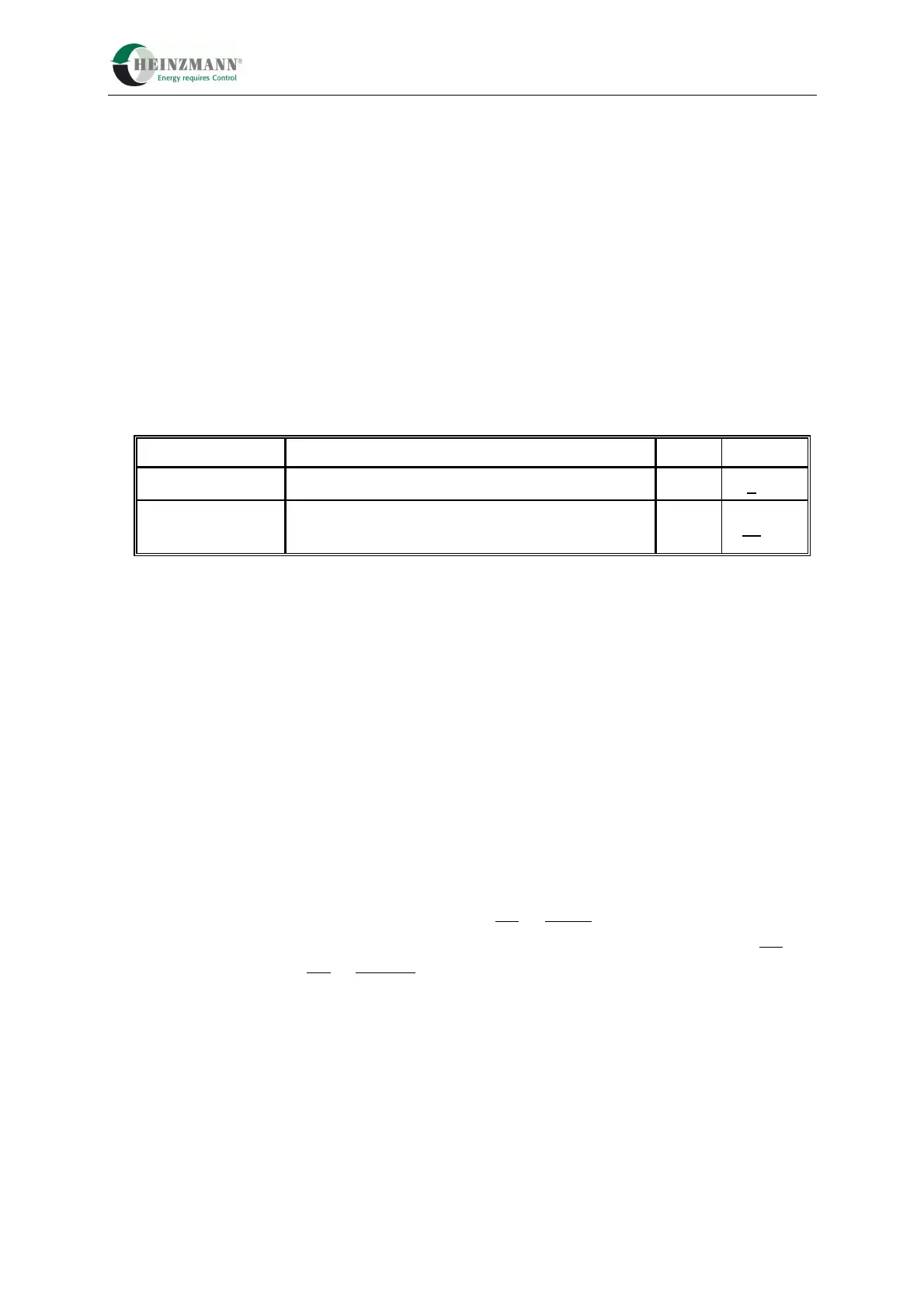
Inputs Use Name Terminal
Digital input 4 unassigned SpD 9, 21
Digital input 5
*
Digital input unless PWM setpoint and
analogue stop are simultaneously requested
Stp 11, 21
*
optional PWM input(
4.1.2 PWM Setpoint)
Table 7: Digital Inputs
In the HEINZMANN control units a distinction is made between external switches (digital
inputs) and internal switch functions. This means that although the system control is
determined by the current value of switch functions, the actual configuration which gives
these switch functions their value takes place separately.
For every switch function there is a display parameter which indicates whether the function
is activated. A “1” always means that the function is active, whereas a “0” means it is
inactive. This display is independent of the hardware configuration of the switches (high
side/low side).
The switch functions used in the PANDAROS DC 6-06 are on/off switches. The name of
the switch function corresponds to the meaning On or Active, i.e. 2810 SwitchStopRequest
= 1 means that a stop request is present, for example. The state “1” always defines On and
the state “0” stands for Off or Inactive.
The following table gives an overview of the existing switch functions. Explanations of the
individual functions and switch priorities will be found in the corresponding chapters of
the function descriptions.
 Loading...