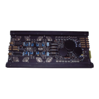
21
Jumper positions for extended adjustment range:
Jum-
per
Posi-
tion
Value range
A2Highlevel
A - D: 10 – 20 Volt
RCA A - D: 4 – 8 Volt
B2Highlevel E - F: 10 – 20 Volt
RCA E - F: 4 – 8 Volt
7KHVHQVLWLYLW\UDQJHRIWKHSUHDPSOL¿HULQSXWV
E and F can also be changed to connect even
PRELOH
GHYLFHV ZLWK VLJQL¿FDQWO\ ORZHU RXWSXW
voltage (like smartphones) by repositioning
jumper B. The input sensitivity is adjustable
from 170 mV to 340 mV if jumper B is inserted
into the marked position in the picture below.
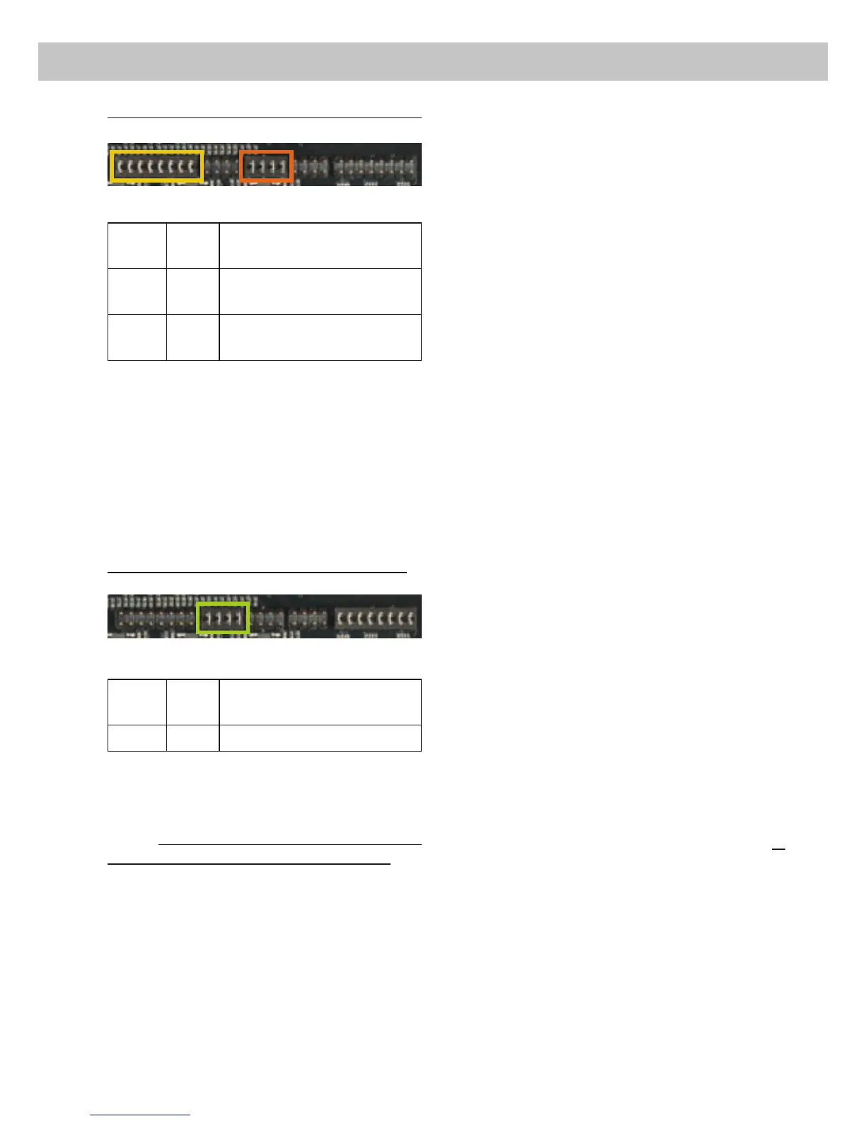
AUX jumper position for RCA inputs E and F:
Jum-
per
Posi-
tion
Value range
B3
RCA E – F: 170 mV – 340 mV
Important: To change the position of a jumper
it has to be removed by pulling it straight up-
wards. Make sure that the jumper is reinsert-
ed properly and all pins are fully inserted. The
position of each jumper can be changed inde-
pendently.
Follow the subsequent steps if you like to per-
IHFWO\ DGDSW WKH DPSOL¿HUV LQSXW VHQVLWLYLW\ WR
your audio source by using the potentiometers:
'RQµW FRQQHFW DQ\ DPSOL¿HUV RU ORXG-
speakers to the outputs of the HELIX
P SIX DSP MK2 during this setup.
2. Adjust the volume of your radio to approx.
90 % of the max. volume and playback a
1 kHz full scale test tone (0 dB) via CD
drive.
3. The adjustment will be easier when you
connect and adjust one input channel after
each other.
4. If the Clipping LED already lights up, you
have to reduce the input sensitivity via
the respective potentiometer until the LED
turns off.
If the potentiometer is already set to maxi-
mum CCW position then it will be necessary
to change the sensitivity range by reposi-
tioning the internal jumper.
5. Increase the input sensitivity by turning the
respective potentiometer clockwise until the
LED lights up. Now turn the potentiometer
counterclockwise until the Clipping LED
turns off again.
6. Repeat this process for each channel pair
you are using.
4. Connecting a digital signal source
If you have a signal source with an optical digital
RXWSXW\RXFDQFRQQHFWLWWRWKHDPSOL¿HUXVLQJ
the appropriate input.
,Q VWDQGDUG FRQ¿JXUDWLRQ WKH +(/,;
P SIX DSP MK2 automatically activates the
used digital input if a digital audio signal is de-
tected. This function can be deactivated via the
DSP PC-Tool software. Alternatively you can
manually activate the digital input if you are us-
ing the optional remote control. The automatic
turn-on circuit does not work when the digital in-
put is used. Therefore it is mandatory to connect
the remote input (REM).
Please note that it is possible to connect a
source to the digital input and the highlevel or
WKHSUHDPSOL¿HUDWWKHVDPHWLPH
Important: The signal of a digital audio source
normally does not contain any information
about the volume level. Keep in mind that this
will lead to full level on the outputs of the HELIX
36,;'630.DQG\RXUFRQQHFWHGDPSOL¿HUV
This may cause severe damage to your speak-
ers. We strongly recommend to use an optional
remote control for adjusting the volume level of
the digital signal input!
B3
A2 B2
 Loading...