NETLink
®
Ethernet Products
2 Installation and mounting
Installation and mounting must be carried out in accordance with
VDE 0100 / IEC 364. As this is an IP20 module, it must be
installed in a cabinet.
A maximum ambient temperature of 60 ºC must be ensured for
reliable operation.
2.1 Mounting orientation
All NETLink
®
can be installed in any orientation.
2.2 Minimum spacing
By maintaining minimum spacings
• then NETLink
®
Gateways can be inserted and removed
without having to remove other system components.
• there is sufficient space to connect existing interfaces and
other contacts using standard commercial type accessories.
• there is room for any necessary cable routing.
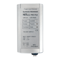
For a NETLink
®
PRO PoE, NETLink
®
Switch and a NETLink
®
WLAN
a minimum clearance of 60 mm must be left above and below
and 10 mm at the sides.
2.3 Installing the module
2.3.1 NETLink
®
PRO PoE and NETLink
®
WLAN
A wall/DIN rail bracket is available as an accessory for mounting
on flat surfaces or on DIN rails.
The accessories available are listed in Section 3.5, together with
the corresponding order numbers.
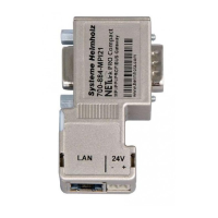
2.3.2 NETLink
®
PRO Compact
The NETLink
®
PRO Compact is plugged directly into the SUB D
female connector of the PROFIBUS station instead of the standard
PROFIBUS device connector. It is fixed using the permanently in-
tegrated hexagon-head housing screws and therefore makes per-
manent contact.
Further bus nodes for diagnostic devices can be connected to the
integrated PG female connector.
Only CAT5-TCP cables with an RJ45 connector can be connected
to the NETLink
®
PRO Compact housing. No further outlets, for
example, PROFIBUS cable, can be installed on the device. There-
fore no termination is possible on the connector housing and the
"ON/OFF" switch for this is not been incorporated.
Before you start
installation work, all
system components
must be disconnected
from their power source.
 Loading...