MBX-4 User Guide
23
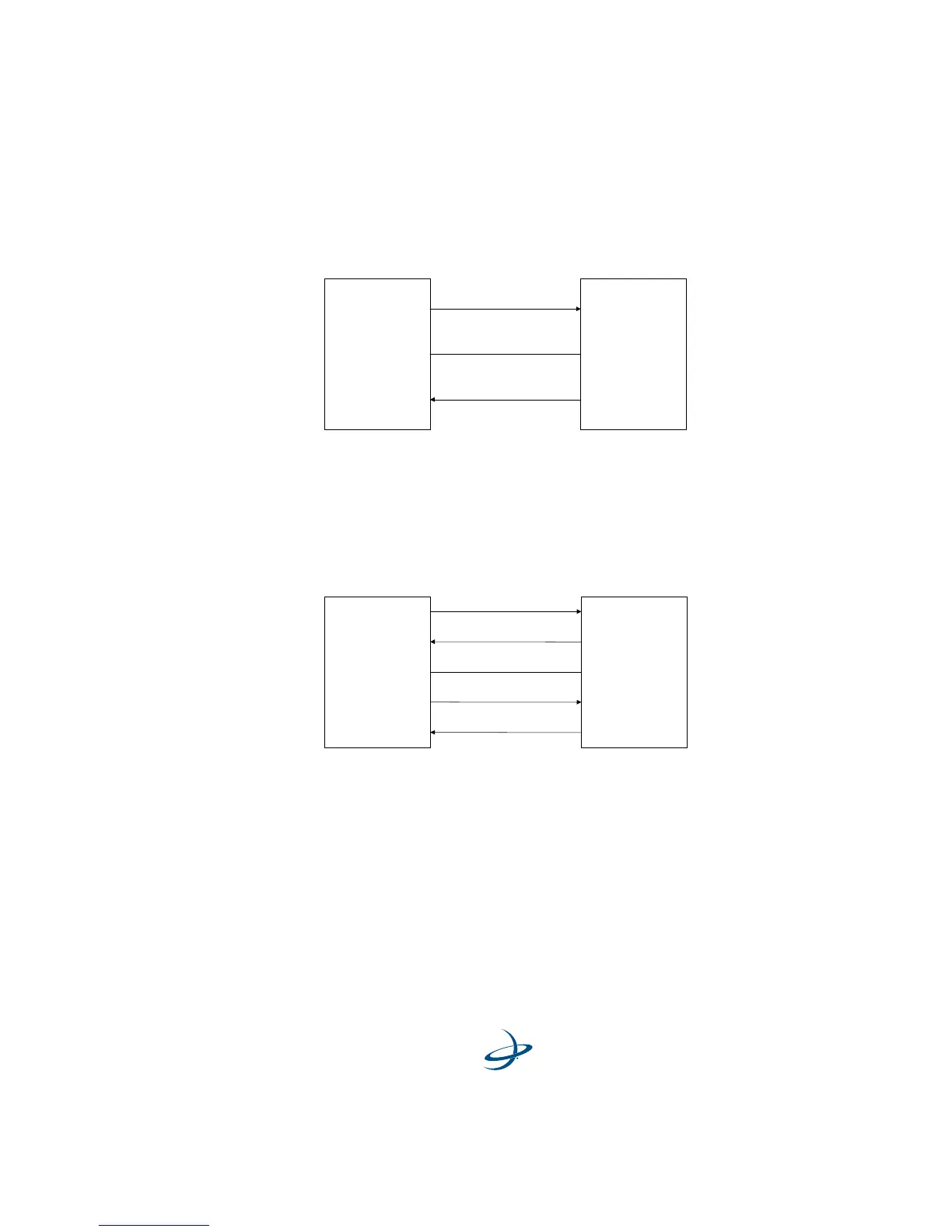
Figure 2-2 illustrates this requirement for a GPS receiver operating at
the RS-232 communications level:
Figure 2-2. Receiver I/O Interface, RS-232
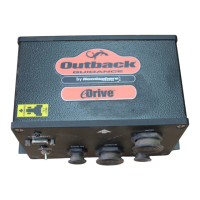
Figure 2-3 illustrates this requirement for a GPS receiver operating at
the RS-422 communications level:
Figure 2-3. Receiver I/O Interface, RS-422
For successful communications, the baud rate of the beacon receiver
must be set to match that of the GPS receiver. Refer to the “Change
Baud Rate” section on page 51 for instructions set the MBX-4 baud rate
using the display and keypad, and the “MBX-4 Port Rate Command
($PCSI,6)” section on page 63 for information to change the baud rate
using proprietary NMEA commands.
MBX-3S
Pin 2 - Tx
GPS
Pin 3 - Rx Tx
Rx
Signal Ground
Pin 5 - Gnd
Gnd
MBX-3S
Pin 1 - Tx +
GPS
Pin 7 - Rx + Tx +
Rx +
Signal Ground
Pin 2 - Tx -
Pin 4 - Rx - Tx -
Rx -
Pin 5 - Gnd Gnd