V103/113 Vector User Guide Chapter 2-Installation Page 12 of 35
Complete the following steps to flush mount the V103/113:
1. Determine the desired location and proper orientation for theV103/113. See “Mounting Orientation” for
information on determining the desired orientation.
2. Navigate to the HGNSS websiteV103: Home / Products / Products / Position & Heading / V103 and
V113 https://hemispheregnss.com/Products/Products/Position-Heading/vector-v103e284a2-and-
v113e284a2-gps-compasses-96
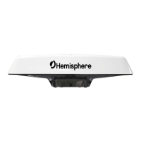
3. Use the supplied template or photocopy the section of the V103/113 that contains the eight mounting
holes (see Figure 2-7) for use as a template to plan the mounting hole locations. Use the inner four
holes or the outer four holes per your installation.
4. If using a photocopy, make sure it is scaled one-to-one with the mounting holes on the bottom of the
V103/113.
5. Mark the mounting hole centers on the mounting surface.
6. Place the V103/113 over the marks to ensure the planned hole centers align with the true hole centers
(adjusting as necessary).
7. Use a center punch to mark the hole centers.
8. Drill the mounting holes with a 9mm bit appropriate for the surface.
9. Place the V103/113 over the mounting holes and insert the mounting screws through the bottom of the
mounting surface into the V103/113.
When installing the V103/113, hand-tighten only. Damage resulting from
overtightening is not covered by the warranty.
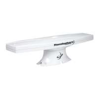
Pole Mounting the Vector Compass
If you need the GNSS-assisted roll measurement, install the V103/113 perpendicular to the vessel’s axis. If you
do not need this measurement, install the V103/113 parallel with the vessel’s axis. For more information refer
to Figure 2-2 and Figure 2-3.
Complete the following steps to pole mount the V103/113:
1. Determine the desired location and proper orientation for theV103/113. See “Mounting Orientation” for
information on determining the desired orientation.
2. Hand tighten the V103/113 on the pole until snug (unit is stable on pole) while ensuring correct
orientation.
Hand tighten only. Damage resulting from over-tightening is not covered by the
warranty.
3. Use the set screws on the long sides of the base (see Figure 2-6) to secure the V103/113 in place
(3/16" Allen wrench not included).