V103/113 Vector User Guide Chapter 2-Installation Page 23 of 35
Power/Data Cable Pinout Specifications
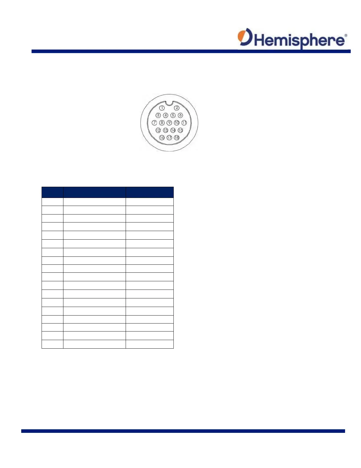
Figure 2-11 shows the power/data cable pinout, while Table 2-3 shows the cable’s pinout
specifications.
Figure 2-11: Power/Data Cable Pin Assignment
Table 2-3: Power/Data Cable Pinout
Pin Function Wire Color
1
Power (+) Red
2
Power (-) Black
3
Port A Tx RS-232 Blue
4
Port A Rx RS-232 Black/blue stripe
5
Reserved
6
Port A Tx RS-422(+) Green
7
Port B Rx RS-422(+) Brown
8
Port B Rx RS-422(-) Black/brown stripe
9
Reserved
10 Drain Bare wire
11 Port A Tx RS-422(-) Green/black stripe
12 Signal ground Grey
13 Alarm White
14 Alarm White/red stripe
15 1 PPS(+) Orange
16 Port B Tx RS-422(+) Yellow
17 Port B Tx RS-422(-)
Yellow/black stripe
18 1 PPS(-) Orange/black stripe