V103/113 Vector User Guide Chapter 3 - Operation Page 28 of 35
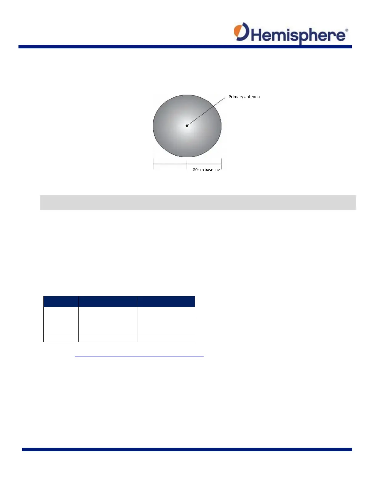
The V103/113 restricts the RTK solution. It does this knowing that the secondary GNSS antenna is 50 cm from the
primary GNSS antenna. This is called a fixed baseline and it defines the search volume of the secondary antenna
as the surface of a sphere with radius 50 cm centered on the location of the primary antenna (see Figure 3-1).
Figure 3-1: Secondary Antenna’s Search Volume
Note: The V103/113 moving base station algorithm only uses GNSS to calculate heading. Differential corrections
are not used in this calculation and will not affect heading accuracy.
Supplemental Sensors
The V103/113 has three supplemental sensors (gyro and two tilt sensors) that are integrated into the unit’s carrier
board. The supplemental sensors are enabled by default. You can enable/disable the gyro and both tilt sensors
(you cannot enable/ disable each tilt sensor separately).
The sensors act to reduce the RTK search volume, which improves heading startup and reacquisition times. This
improves the reliability and accuracy of selecting the correct heading solution by eliminating other possible,
erroneous solutions. Table 3-1 provides a sensor operation summary.
Table 3-1: Sensor Operation Summary
Feature Normal Operation Coasting (no GPS)
Heading GNSS Gyro
Heave GNSS None
Pitch GNSS Inertial sensor
Roll Inertial sensor Inertial sensor
Refer to the Hemisphere GNSS Technical Reference Guide for the commands and methodology required to
recalibrate, query, or change a sensor’s status.