EasyManua.ls Logo

Hesai PandarQT - Lidar Structure

Hesai PandarQT
66 pages
Print Icon
To Next Page IconTo Next Page
To Previous Page IconTo Previous Page
Loading...
2
1.2 LiDAR Structure
Laser emitters and receivers are attached to a motor that rotates horizontally.
Figure 1.2 Partial Cross-Sectional Diagram
Figure 1.3 Coordinate System (Isometric View)
Figure 1.4 Rotation Direction (Top View)
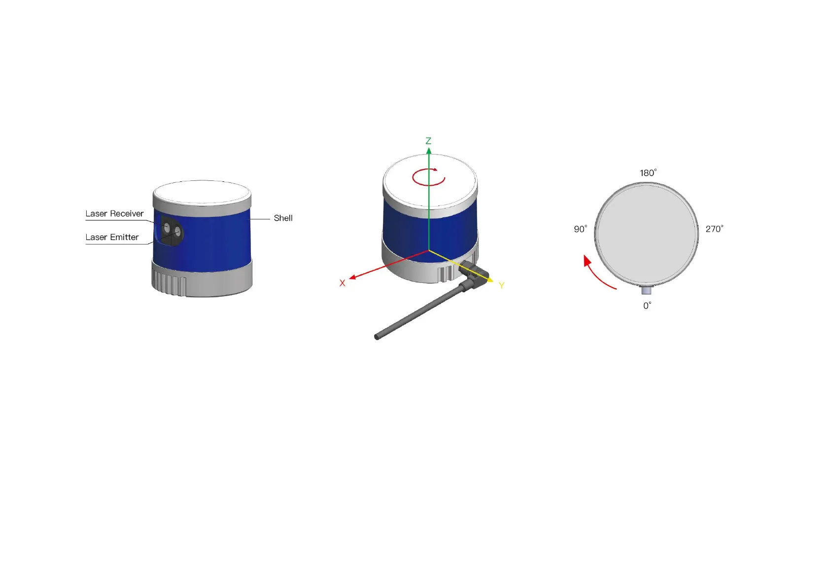
The LiDAR’s coordinate system is shown above. The Z-axis is the axis of rotation.
The origin is shown as a red dot in Figure 1.6 on the next page. After geometric transform, all the measurements are relative to the origin.
When the horizontal center of the emitter-receiver array passes the zero-degree position illustrated in Figure 1.4, the azimuth data in the corresponding
UDP data block will be 0°.

Other manuals for Hesai PandarQT

Related product manuals