6. MODULE HARDWARE DESCRIPTION
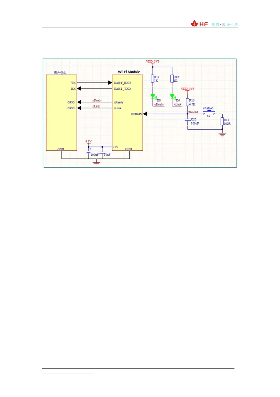
The typical wiring of the module is shown below.
nLink- (optional, general debugging) Module WIFI connection indication, batch
upgrade, configuration status indication, output.
If the module is set to STA mode and successfully connected to the AP, the output low
level can be used to determine whether the module is in a networked state. There is a
pull-up resistor inside, no external pull-up resistor is required. If you do not need to use
this pin function, leave it unconnected, ie no connection is required.
nReady- (optional, for general debugging) The module completes normal startup and
output.
When the module starts normally, the output low level can be used to judge whether
the module starts normally and works in the normal mode; if the pin function is not needed,
it is left floating, that is, no connection is needed.
nReload- (recommended, important function) Restore factory default settings, batch
upgrade, SmartAPLink distribution network, input, active low. It can be connected to an
external button or chip pin. When the button is pressed, pull the pin low, release it after 4
seconds, the module is restored to the factory settings, and then restarted. If you do not
need to use this pin function, you can hang it.
UART0_TXD/RXD (required) - Serial data transmission and reception signal.
6.1. Serial Port Level Conversion
◆ Triode tube compression (recommended)
If the RX pin of the user equipment considers 3.3V to be high, it can be directly
connected.
 Loading...