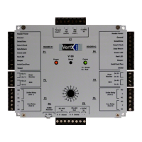
VertX V1000 (CS) Quick Installation Guide
2. Serial (RS-232) Adapter cable (P/N 70007) – The Serial Adapter cable is included with the V1000
controller.
The Serial Adapter cable is a six inch adapter that converts the 9 pin MTA header to a standard
DB-9 male connector. This adapter is to be utilized for attaching a standard RS-232 serial modem
cable (not included) to the VertX controller. This will allow one of the approved external modems
(listed in
1.5.1 Modem Setup Requirements, page 10) to be attached to the V1000.
The following table shows the P17 pin settings.
Pin # P17
1 DCD
2 RX
3 TX
4 DTR
5 GND
6 DSR
7 RTS
8 CTS
9 RI
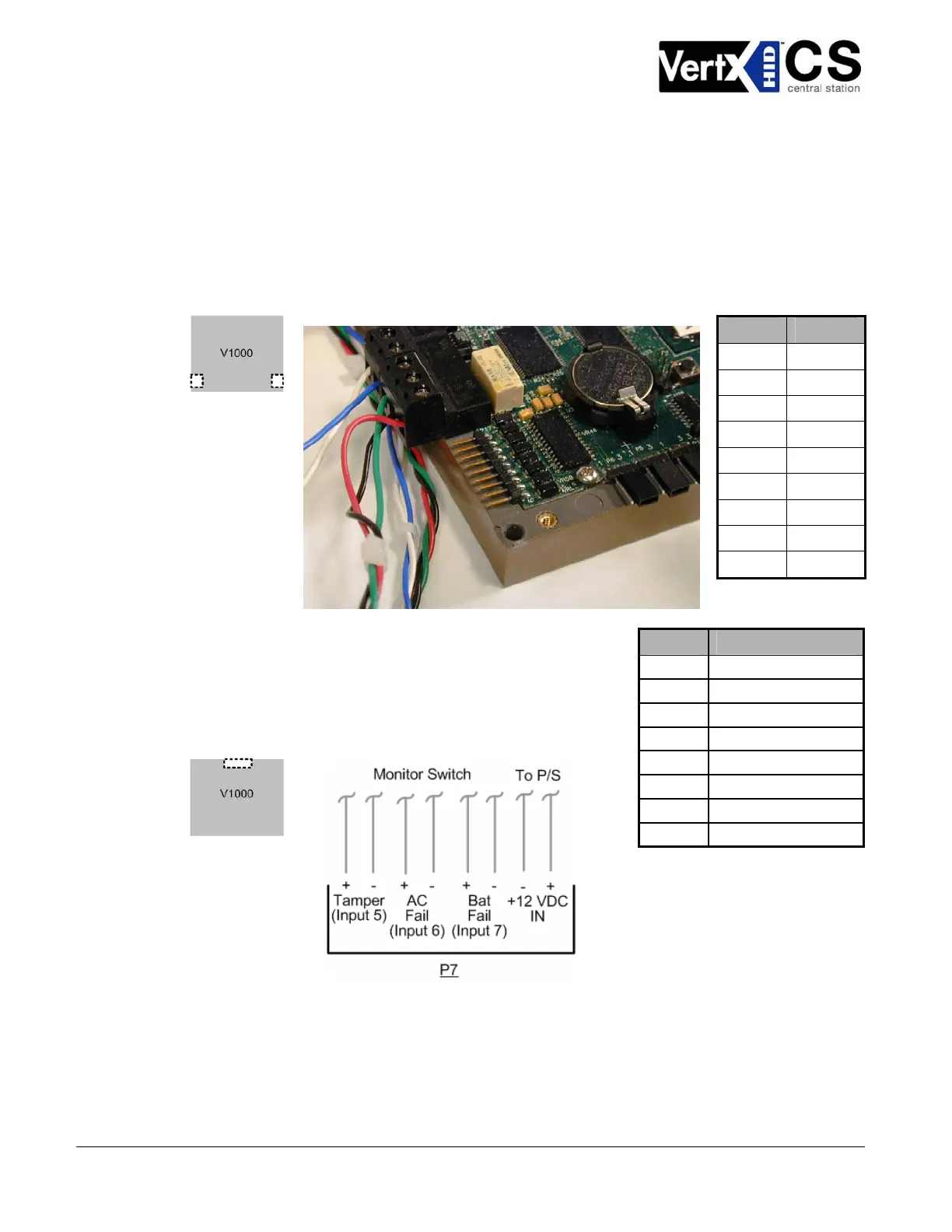
3. Power and Alarm Input connections: Connect power by
providing 12VDC to the
Pin # P7
P7 connector. +12VDC goes to Pin 1
and ground to Pin 2. Bat Fail, AC Fail, and Tamper switch inputs
are wired as shown in the table. Connect the Bat Fail and AC Fail
inputs to the battery low/failure and AC failure contacts on the
power supply. Connect the Tamper input to a tamper switch on
the enclosure.
1 +12VDC
2 Ground
3 Bat Fail -
4 Bat Fail +
5 AC Fail -
6 AC Fail +
7 Tamper -
8 Tamper +
October 2006 Page 6 of 20
© 2006 HID Global Corporation. All rights reserved.