5. Servo operating
5-9
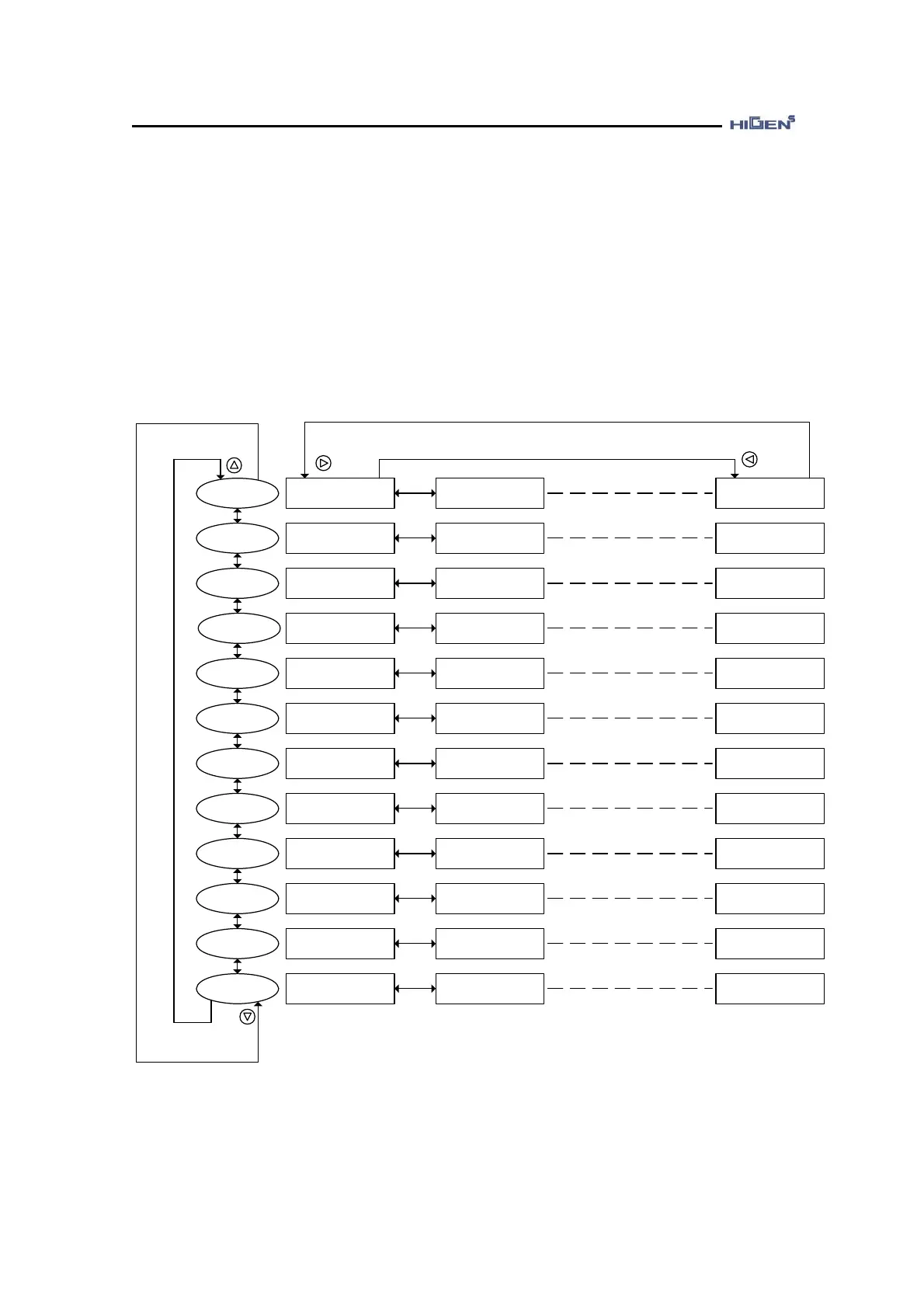
5.3 Operation of digital loader
5.3.1 Display flow
If the power is supplied and connected to digital loader correctly, LCD window of the digital
loader display a message. The digital loader has LCD window and function key on front panel.
You can set the parameter, display the status, check the sequence and alarm record by the
loader. The following diagram shows an overview aspect for digital loader menu.
STATUS
WINDOW
DOWN KEY
UP KEY
LEFT KEY
RIGHT KEY
Display Select
StE-01 1203
MOTOR
PARAMETER
CONTROL MODE
SPEED MODE
DIGITAL MODE
POSITION MODE
TORQUE MODE
INPUT MODE
OUTPUT MODE
MONITOR MODE
JOG MODE
ALARM WINDOW
Command Speed
StE-02 3000
PROG Version
StE-18 1.00
Motor ID
P01-01 14
Inertia
P01-02
Absolute Origin
P01-20 OFF
Control Mode
P02-01 1
Mode Change Time
P02-02 500.0
Parameter INIT
P02-29 OFF
Speed Gain Mode
P03-01 1
PI-IP Control %
P03-02 100.0
Feedforward TRQ
P03-24 0
Speed1
P04-01 10.0
Speed2
P04-02 100.0
Torque7
P04-14 120.0
POS Gain Mode
P05-01 1
POS Pulse Type
P05-02 1
Backlash Pulse
P05-22 0
Analog TRQ TC
P06-01 0.0
TRQ ACCEL Time
P06-02 0.0
Manual Offset
P06-09 0.0
CN1_18
P07-01 1
CN1_43
P07-02 9
CN1_38
P07-12 19
CN1_23
P08-01 1
CN1_48
P08-02 7
CN1_44
P08-10 18
Monitor1
P09-01 0
Monitor ABS1
P09-02 OFF
Monitor Offset2
P09-08 0.0
Key Jog Mode
JOG-01 OFF
Key Jog Speed
JOG-02 100.0
Jog Time8/REV8
JOG-19 1.0
Current Alarm
ALS-01 0
Alarm Reset
ALS-02 OFF
History Reset
ALS-13 OFF