4. Servo using method and gain adjustment
4-1
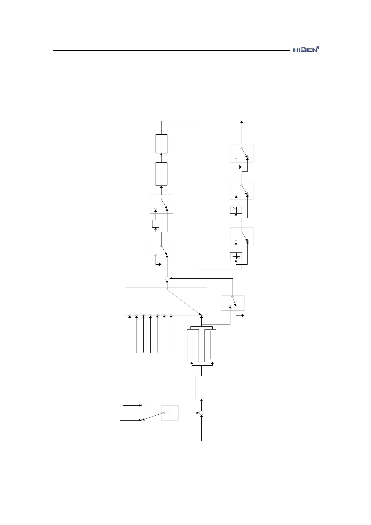
4.1 Gain adjustment method for speed control mode
This explains the gain adjustment method when using speed servo. The following diagram
shows the generation sequence of the speed command in speed control.
1000
1
[Offset voltage setting
(P03-18)]
Clamp
Mode
[Clamp mode setting(P03-20)]
[Clamp voltage setting(P03-21)]
[+10V Speed (P03-15)]
10
[Digital input speed1(P04-01)]
Speed command selection
(SPD1,SPD2,SPD3)
(ON,OFF,OFF)
(OFF,ON,OFF)
(OFF,OFF,OFF)
(ON,ON,ON)
(OFF,ON,ON)
(ON,OFF,ON)
(OFF,OFF,ON)
(ON,ON,OFF)
Stop command
(STOP)
(ON)
(OFF)
GND -1
Revolution direction
(DIR)
Acceleration /
deceleration
process
[Acceleration time (P03-10)]
[Deceleration time (P03-11)]
S - mode
operation
[S - moed operation TC
(P03-12)]
Override mode
[Override mode operation (P03-19)]
[1]
[0]
GND
+
+
+
(SPD1,SPD2,SPD3)=(OFF,OFF,OFF)
Note) Override operation stop when
( ) : Contact point input
[ ] : Set value
(SPDIN)
CCW revolution limit
(CCWLIM)
Emergency stop
(ESTOP)
GND
Internal
speed command
+
[Offset voltage
auto adjustment(P03-17)]
[Digital input speed2(P04-02)]
[Digital input speed3(P04-03)]
[Digital input speed4(P04-04)]
[Digital input speed5(P04-05)]
[Digital input speed6(P04-06)]
[Digital input speed7(P04-07)]
(ON)
(OFF)
(ON)
(OFF)
(ON)
(OFF)
CW revolution limit
(CWLIM)
(ON)
(OFF)
[-10V Speed (P03-16)]
10