4. Servo using method and gain adjustment
4-2
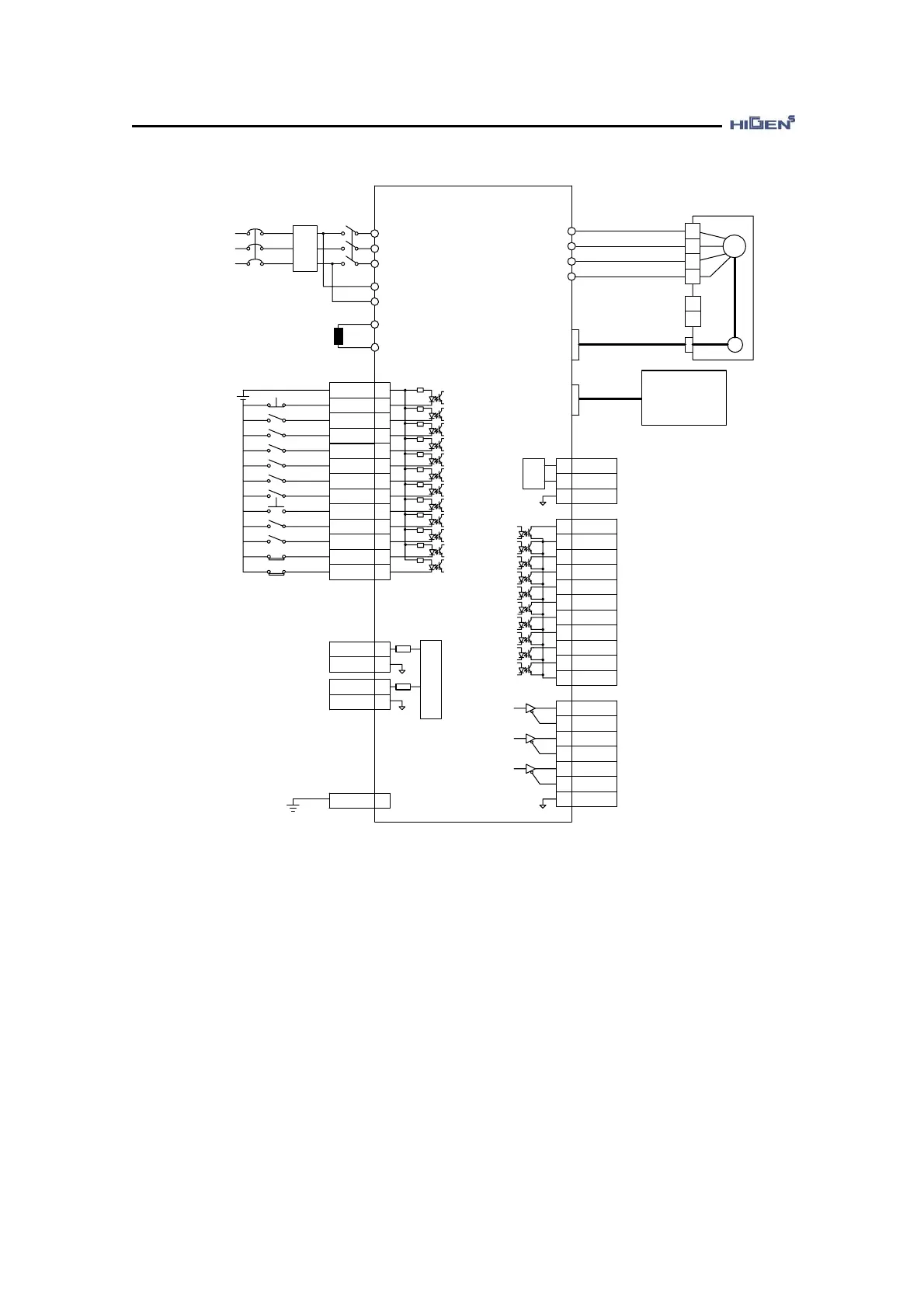
4.1.1 CN1 wiring diagram for speed control servo
Servo Drive
FDA7000
R
S
T
r
t
P
B
CN1
(input)
+24V
ESTOP
SPD1/
GEAR1
SPD2/
GEAR2
SPD3
DIR
STOP
SVONEN
ALMRST
SPDLIM/
TLIM
PI/P
CWLIM/
NTQLIM
CCWLIM/
PTQLIM
SPDIN
GND
TRQIN
GND
49
17
41
15
40
14
43
18
42
38
16
13
39
27
1
33
28
34
36
3.3K
+
-
+24V
U
V
W
FG
SM
+
-
Brake power
input terminal
U
V
W
FG
PG
CN2
CN3
MONIT1
MONIT2
GND
SVONOFF
INSPD/INP
OS/INTRQ
BRAKE
RDY
ZSPD
SPDOUT/
TRQOUT
ALARM
PCWOUT/
PTQOUT
NCWOUT/
NTQOUT
PPIOUT
GND24
PAO
/PAO
PBO
/PBO
PZO
/PZO
GND
3
2
8
26
23
47
48
22
19
21
46
20
45
44
24
25
7
32
6
31
5
30
8
26
CN1
(output)
A/D
D/A
NF
Power AC 200~230V
50/60Hz
NFB MC1
Regenerated
resistor
*Digital Loader
*PC Loader(RS232C)
*Network communication
(RS485, RS232C)
(note) 1
(note) 2
FG
50
(note) 4
(note) 3
3.3K
3.3K
3.3K
3.3K
3.3K
3.3K
3.3K
3.3K
3.3K
3.3K
3.3K
LPF
LPF
♥
The above input and output contact points are shown when setting the speed control mode contact
point. (P07-01,P08-01=26).
(Note)
1 : NF stands for Noise Filter and it must be used to prevent the noise from intruding from
the outside.
(Note) 2 : For the FDA7004/7004B~45 type, connect the single phase AC220V[V] to the r, t terminal,
auxiliary power. FDA7001~02 type does not have the auxiliary power r, t terminal.
(Note) 3 : The recovery resistances of FDA7004~FDA7010 are installed inside the driver as an
internal type. The recovery resistance of the FDA7001, 7002, 7004B, FDA7015 type or
above is the separately installed type. Check the capacity and apply accordingly.
(Note) 4 : Connect the ground wire of CN1 cable to the FG (Frame Ground) terminal.
(Note) 5 : Separate GND24 (CN – 24, 25) and GND (CN1 – 1, 8, 26, 33, 34, 36).
When connect commonness, malfunction of servo drive and burnout can occur.