User Manual of 9600/8600/7700/7600 Series NVR
26
Switch for turning on/off the device.
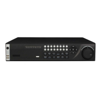
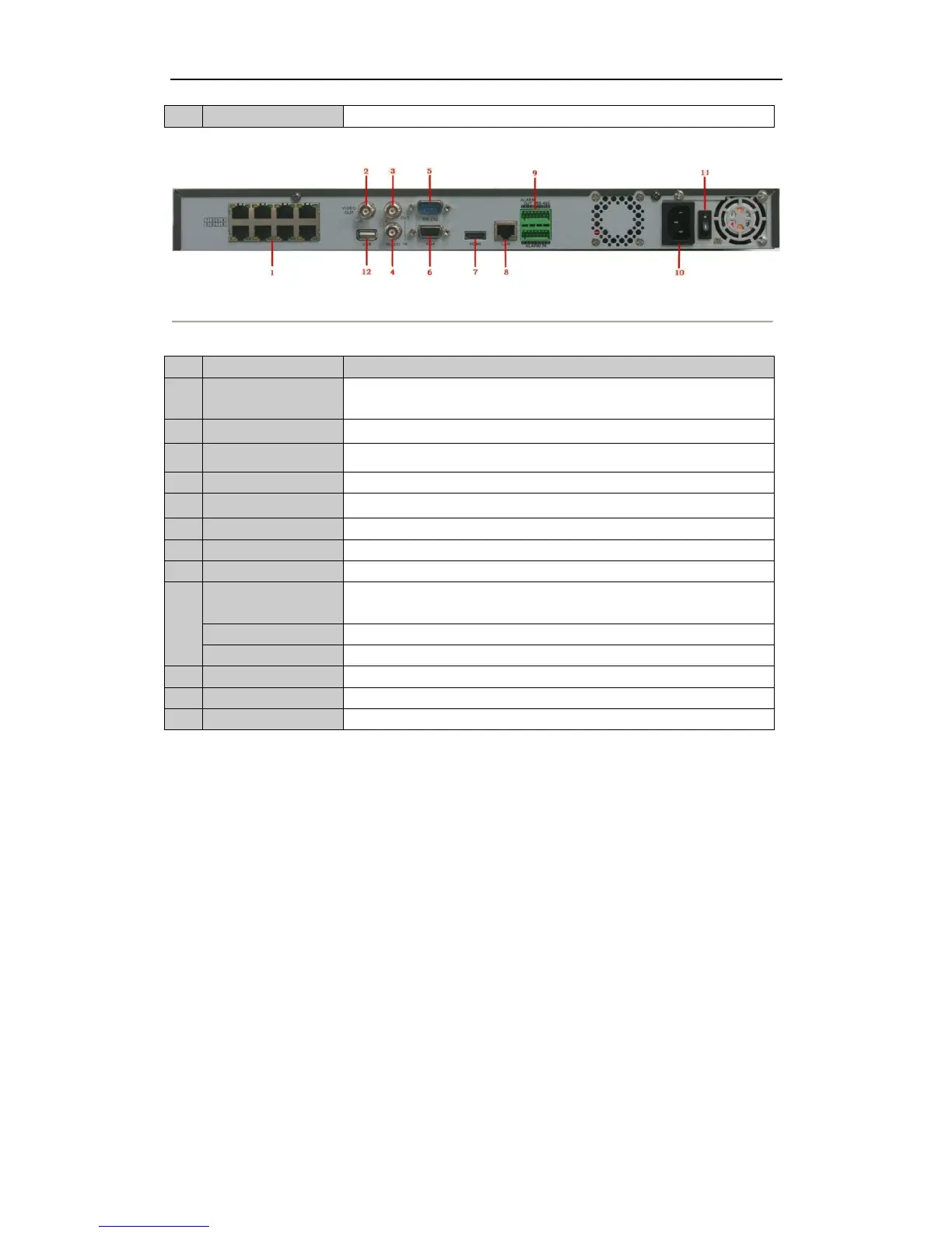
Figure 1. 14 7600-P8
Table 1. 10 Description of Rear Panel Interfaces
Network Interfaces
with PoE function
Network interface for the cameras and to provide power over Ethernet.
BNC connector for video output.
BNC connector for audio output.
BNC connector for audio input. (Also for voice talk)
Connector for RS-232 devices.
DB9 connector for VGA output. Display local video output and menu.
HDMI video output connector.
Connector for LAN (Local Area Network).
Connector for RS-485 devices. T+ and T- pins connect to R+ and R- pins of
PTZ receiver respectively.
Connector for alarm input.
Connector for alarm output.
AC 100V ~ 240V power supply.
Switch for turning on/off the device.
Connects USB disks and devices.
 Loading...