Video Access Control Terminal·User Manual
131
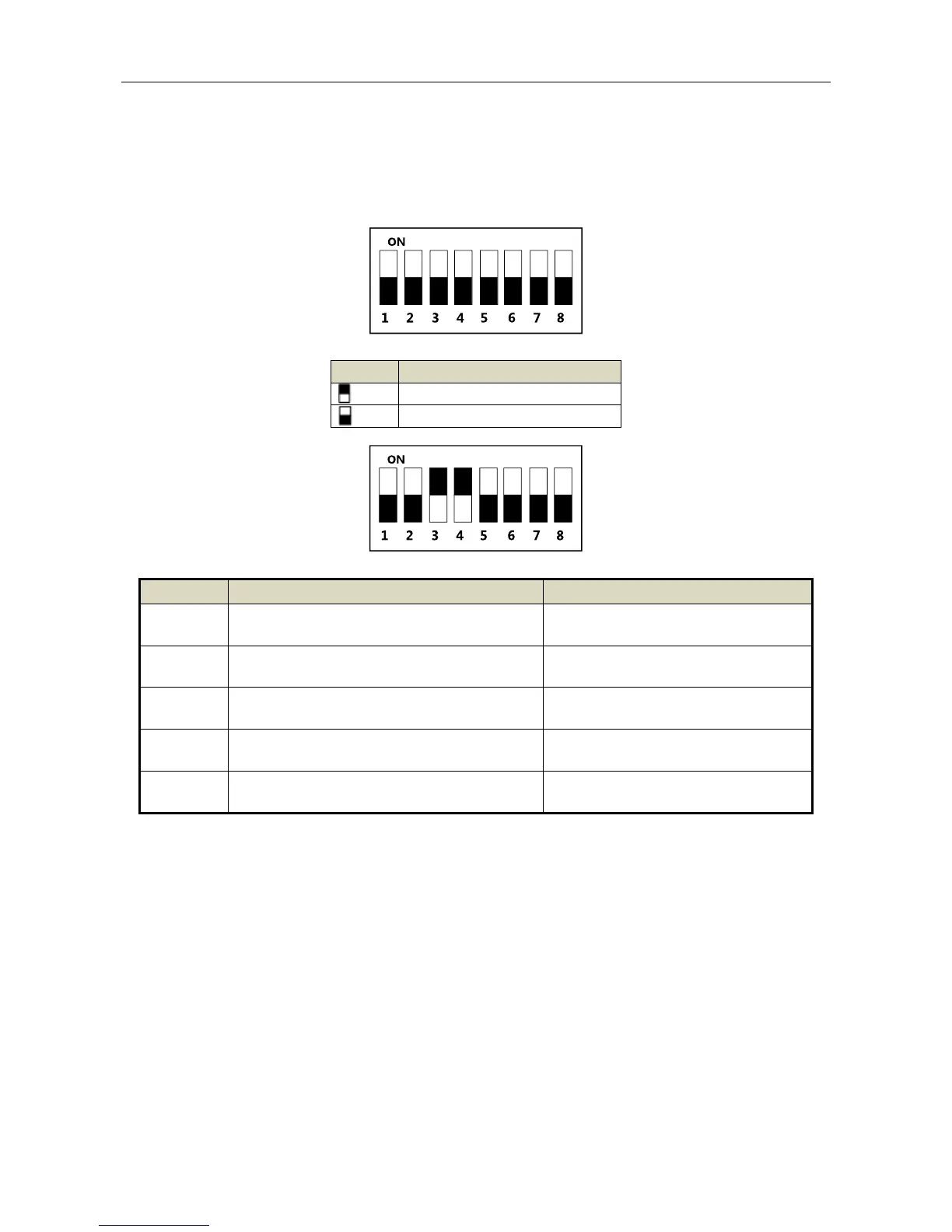
Appendix B DIP Switch Introduction
The DIP switch diagram is as follows:
Table 7-2 Description of DIP Switch
Represent 1 in binary mode
Represent 0 in binary mode
For example, binary value of the following status is: 0000 1100.
Table 7-3 Description of DIP Switch
2: Security Module
0: Card Reader
RS-485 Direction under the Terminal
Mode
1: Upstream;
0: Down Stream
1: Card Reader;
0: Terminal.
Wiegand Protocol
(available when No. 6 is 1)
1: Wiegand protocol of 26-bit;
0: Wiegand protocol of 34-bit.
Matched Resistance
(available for RS-485 protocol)
 Loading...