F1 DI 16 01 3 Product Description
HI 800 153 E Rev. 2.00 Page 11 of 42
3 Product Description
The safety-related F1 DI 16 01 remote I/O is a compact system in a metal housing with
16 digital inputs and 4 pulsed outputs.
The remote I/O is available in various model variants for SILworX and ELOP II Factory, see
Table 4.
Remote I/O
s are connected to individual HIMax or HIMatrix controllers via safeethernet. They
are used to extend the I/O level, but are not able to run any user program by themselves.
The remote I/O is suitable for mounting in Ex-zone 2, see Chapter 4.1.4.
The device is TÜV-certified
for safety-related applications up to SIL 3 (IEC 61508, IEC 61511
and IEC 62061), Cat. 4 and PL e (EN ISO 13849-1) and SIL 4 (EN 50126, EN 50128 and
EN 50129).
Further safety standards, application standards and test standards are specified in the
certificates available on the HIMA website.
3.1 Safety Function
The remote I/O is equipped with safety-related inputs. The input values on the inputs are safely
transmitted to the connected controller via safeethernet.
3.1.1 Safety-Related Digital Inputs
The remote I/O is equipped with 16 digital inputs. The state (HIGH, LOW) of each input is
signaled by an individual LED.
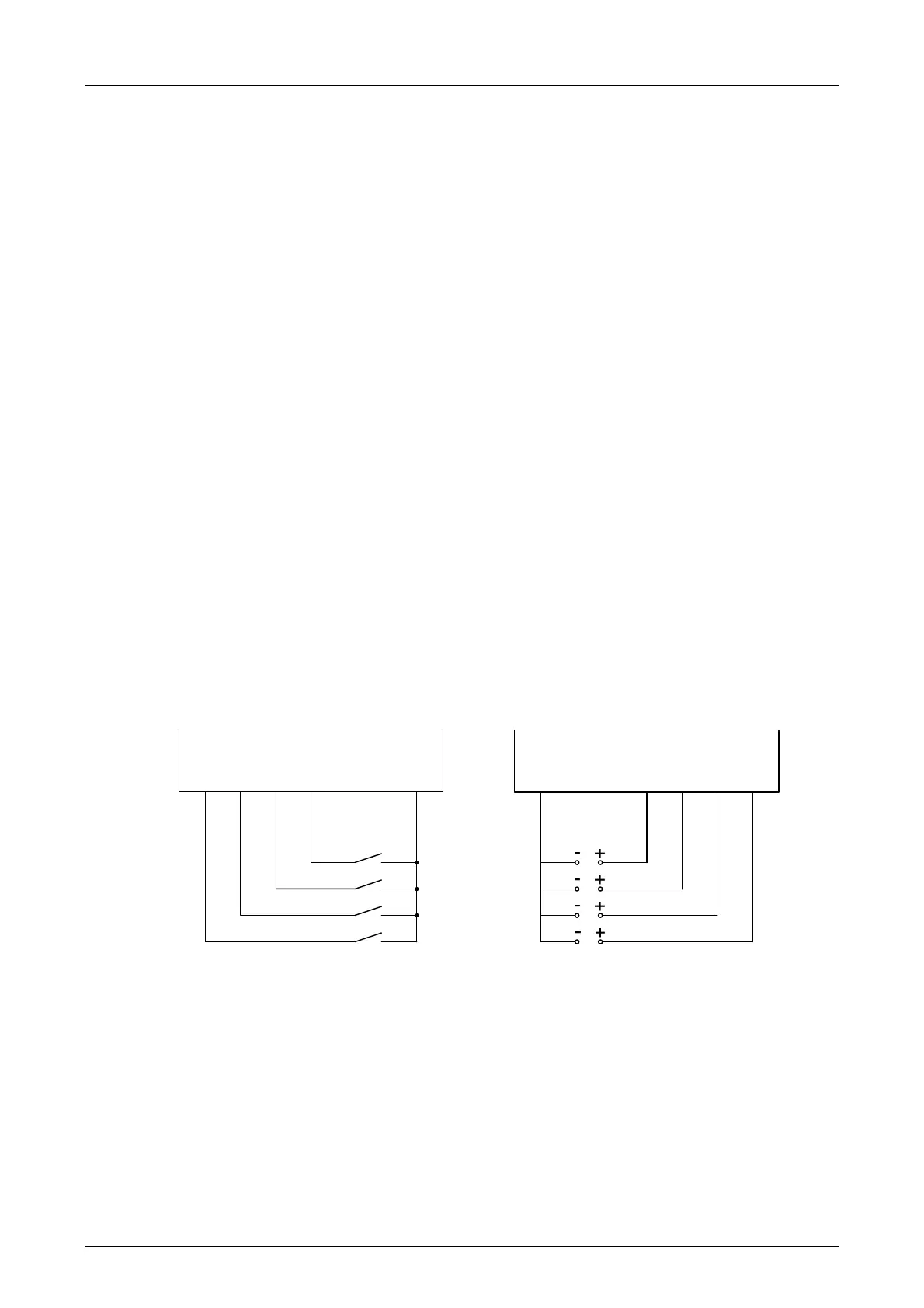
Mechanical contacts without own power supply or signal power source can be connected to the
inputs. Potential-free mechanical contacts without own power supply are fed via an internal
short-circuit-proof 24 V power source (LS+). Each 24 V power source supplies a group of
4 mechanical contacts. Figure 1 shows how the connection is performed.
With sig
nal voltage sources, the corresponding ground must be connected to the input (L-), see
Figure 1.
DI 1
LS+
DI 4
DI 3
DI 2
DI 1
L-
DI 4
DI 3
DI 2
Connection of potential-free mechanical
contacts
Connection of signal power sources
Figure 1: Connections to Safety-Related Digital Inputs
For the external wiring and the connection of sensors, apply the de-energized-to-trip principle.
Thus, if a fault occurs, the input signals adopt a de-energized, safe state (low level).
An external wire is not monitored, however, an open-circuit is considered as safe low level.

 Loading...


