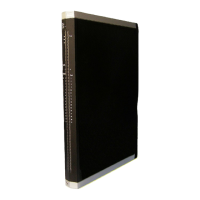
3 Product Description X-DI 64 01
Page 12 of 52 HI 801 093 E Rev. 4.00
3.4 Structure
The module has 64 safety-related digital inputs (24 V) for digital signals, contact makers
and proximity switches (two-wire). For safely detecting a high level on the digital input, the
voltage and current thresholds must be exceeded (see
Table 8).
The eight short-circuit-proof supplies feed eight supply outputs each (S1+ to S8+). One
supply output is assigned to each digital input.
The safety-related 1oo2 processor system for the I/O module controls and monitors the I/O
level. The data and states of the I/O module are made available to the processor modules
via the redundant system bus. The system bus has a redundant structure for reasons of
availability. Redundancy is only ensured if both system bus modules are inserted in the
base plates and configured in SILworX.
The module is equipped with LEDs to indicate the status of the digital inputs, see
Chapter
3.4.2.
3.4.1 Block Diagram
The following block diagram illustrates the structure of the module.
Field Zone: Proximity Switches and Contact
Makers
Interface
Safety-Related Processor System
System Busses
Figure 2: Block Diagram

 Loading...