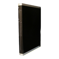
3 Product Description X-DI 64 01
Page 22 of 52 HI 801 093 E Rev. 4.00
Pin no. Designation Signal Pin no. Designation Signal
1 113 S7+ 1 114 S7+
2 49b DI49+ 2 50b DI50+
3 51b DI51+ 3 52b DI52+
4 53b DI53+ 4 54b DI54+
5 55b DI55+ 5 56b DI56+
6 213 DI- 6 214 DI-
7 115 S8+ 7 116 S8+
8 57b DI57+ 8 58b DI58+
9 59b DI59+ 9 60b DI60+
10 61b DI61+ 10 62b DI62+
11 63b DI63+ 11 64b DI64+
12 215 DI- 12 216 DI-
Table 12: Terminal Assignment for Connector Boards with Screw Terminals
Cable plugs attached to the connector board pin headers are used to connect to the field
zone.
The cable plugs feature the following properties:
Connection to the field zone
Cable plugs 8 pieces, with 12 poles
Wire cross-section 0.2…1.5 mm
2
(single-wire)
0.2…1.5 mm
2
(finely stranded)
0.2…1.5 mm
2
(with wire end ferrule)
Stripping length 6 mm
Screwdriver Slotted 0.4 x 2.5 mm
Tightening torque 0.2…0.25 Nm
Table 13: Cable Plug Properties

 Loading...