
 To Next Page
B
Bobby JonesAug 30, 2025
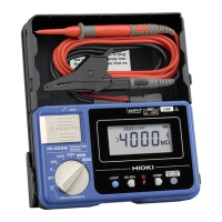
Why do the batteries in my Hioki IR4055 Test Equipment run out so quickly?
- JjasmineclayAug 30, 2025
If the batteries run out immediately, replace the batteries with alkaline batteries if you are not using them.

Why do the batteries in my Hioki IR4055 Test Equipment run out so quickly?
If the batteries run out immediately, replace the batteries with alkaline batteries if you are not using them.
Why does my Hioki IR4055 show different values when measuring the same object repeatedly?
If a different measured value results each time the same measurement object is measured, allow an adequate amount of time (about 1 hour to 1 day) to pass after the first measurement before repeating measurement if there is any impact due to the material of the measuring object. The effects of polarity increase as the insulation resistance increases. Also, measure the object under the same temperature and humidity conditions if there is any impact due to the temperature/humidity characteristics of the measuring object. In general, an insulator’s insulation resistance value will decrease as temperature and humidity increase. As a reference, the insulation resistance value of some insulated cables decreases to 1/4 or less when the temperature increases 10°C.
Why does the insulation resistance range fall outside specifications when calibrating my Hioki IR4055?
If the instrument is calibrated, and the accuracy of the insulation resistance range falls outside the device specifications, use the test leads that came with the instrument or its optional test leads to perform the calibration procedure if the supplied or optional test lead used. With standard wiring, characteristics are affected when the resistance in the 1000 V range reaches or exceeds 100 M?. Also, replace the deteriorated test lead with a new one if the insulation of the test lead deteriorated.
What to do if the measured value is the maximum on Hioki Test Equipment?
If the measured value is shown as the maximum display value, check the continuity of the test lead with a tester if there is a broken connection in a test lead. Also, check the connection between the test leads and the instrument, and check the connection of the tips of the test leads to ensure the test leads are securely connected.
Why is there excessive variation in measured value on my Hioki Test Equipment?
If there is excessive variation in the measured value, disconnect the circuit breaker for any nearby charging circuits if a charging circuit is located near the measurement object. If this is not possible, use the lowest measured value as the measurement result. Also, if the measurement object has a large capacitance component (capacitor), remove the capacitor if possible. If not, use the lowest measured value as the measurement result.
Why does the MEASURE key enable the lock function after being released in my Hioki Test Equipment?
If, in the 500 V range, 1000 V range or PV? range, turning on the MEASURE key enables the lock function that has been released, replace the batteries with new alkaline batteries if the current batteries do not have sufficient charge or are not alkaline batteries. Also, release the lock function again if 1 minute has lapsed after the last operation.
What to do if the live circuit indicator blinks red and the buzzer sounds during insulation resistance measurement with Hioki IR4055?
If, during insulation resistance, low resistance, or PV? measurement, the voltage applied between the measurement terminals exceeds approximately 20 V for insulation resistance and PV?, or approximately 5 V for low resistance, make sure that the measurement target is disconnected from a live circuit. If voltage exists in the measurement target, the live circuit indicator will blink.
 General
| Brand | Hioki |
|---|---|
| Model | IR4055 |
| Category | Test Equipment |
| Language | English |