42
Installation MSP30/32/40/42 and MSM20/22/24/40/42/46/50
Release
12
06/2018
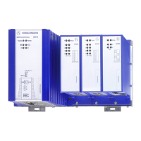
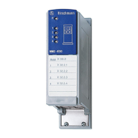
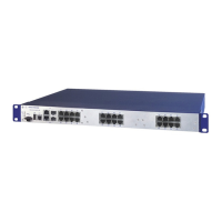
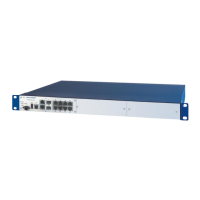
1.8 Display elements
After the supply voltage is set up, the software starts and initializes itself.
Afterwards, the device performs a self-test. During this process, various
LEDs light up.
1.8.1 Device state
These LEDs provide information about conditions which affect the operation
of the whole device.
LED Display Color Activity Meaning
Power Supply voltage — none Supply voltage is too low
yellow Lights up Device variants with redundant power
supply:
Supply voltage 1 or 2 is on
flashes 4 times
a period
Software update is running. Maintain the
power supply.
green Lights up Device variants with redundant power
supply:
Supply voltage 1 and 2 is on.
Device variants with single power supply:
Supply voltage is on
Status Device Status — none Device is starting and/or is not ready for
operation
green Lights up Device is ready for operation.
Characteristics can be configured
red Lights up Device is ready for operation.
Device has detected at least one error in the
monitoring results
Flashes 1 time
a period
The boot parameters used when the device
has been started differ from the boot
parameters saved.
Start the device again.
flashes 4 times
a period
Device has detected a multiple IP address
RM Ring Manager — none No redundancy configured
green Lights up Redundancy exists
Flashes 1 time
a period
Device is reporting an incorrect
configuration of the RM function
yellow Lights up No redundancy exists
ACA Storage medium
ACA
— none ACA storage medium not connected
green Lights up ACA storage medium connected
Flashes 3
times a period
Device writes to/reads from the storage
medium
yellow Lights up ACA storage medium inoperative
 Loading...
