15
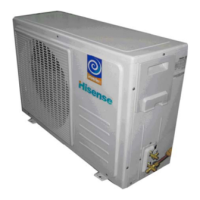
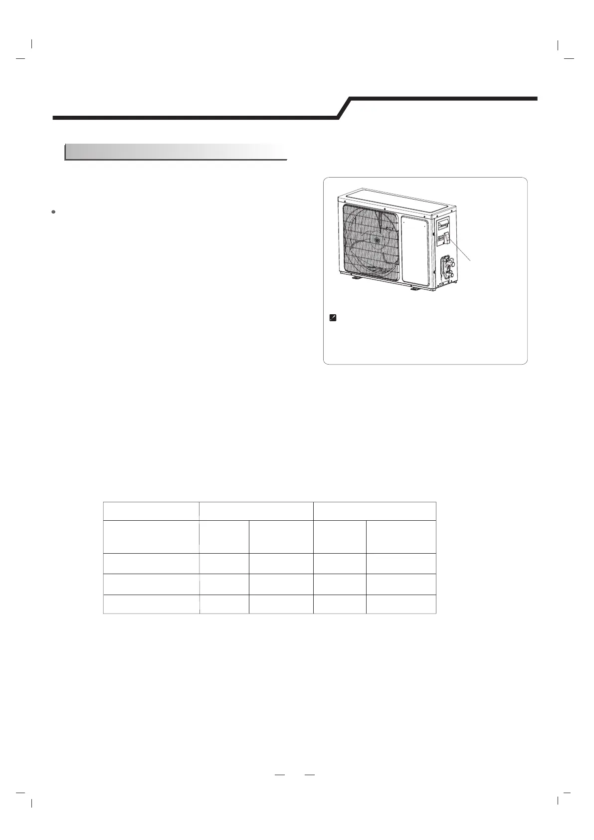
Outdoor Unit
1) Remove the access door from the unit by loosening
the screw. Connect the wires to the terminals on the
control board individually as follows.
2) Secure the power cord onto the control
board with cable clamp.
3) Reinstall the access door to the original position
with the screw.
4) Use a recognized circuit breaker for 24K model between
the power source and the unit. A disconnecting device to
adequately disconnect all supply lines must be fitted.
Note: For some models, it is necessary to remove the cabinet to
connect to the indoor unit terminal.
Access door
Terminal(inside)
Outdoor unit
Installation instructions
Caution:
1. Never fail to have an individual power circuit specifically for the air conditioner. As for the method of
wiring, refer to the circuit diagram posted on the inside of the access door .
2. Comfirm that the cable thickness is as specified in the power source specification.
3. Check the wires and make sure that they are all tightly fastened after cable connection.
4. Be sure to install an earth leakage circuit breaker in wet or moist areas.
The figures in this manual are based on the external
view of a standard model. Consequently, the shape
may differ from that of the air conditioner you have
selected.
Capacity (Btu/h)
Power connecting cord
Power cord
Type Type
Normal cross
- sectional area
Normal cross
- sectional area
Cable Specifications
Attention:
The plug must be accessible even after the installation of the appliance in case there is a need to
disconnect it. If not possible, connect appliance to a double-pole switching device with contact
separation of at least 3 mm placed in an accessible position even after installation.
7K,9K,12K
H07RN-F
2
1.0mm X3
H07RN-F
2
1.0mm X5
18K
24K
H07RN-F
H07RN-F
2
1.5mm X3
2
2.5mm X3
H07RN-F
H07RN-F
2
1.5mm X5
2
2.5mm X5
Connecting of the Cable
 Loading...