Introduction 1-9
Hitachi Compute Rack 220H CRU Replacement Guide
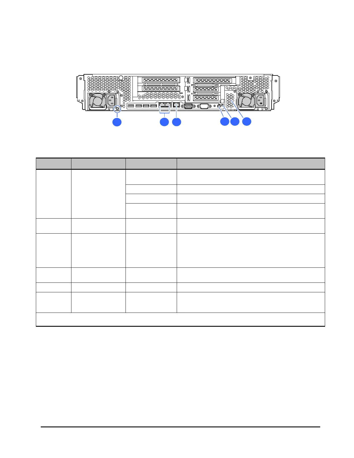
Rear side
Figure 1-6: CR 220H rear side overview
Table 1-7: CR 220H rear side indicators
Location Name State Description
1 Power supply LED
Green-Blink
AC power is supplied / Stand-by state (AC cable is connected,
POWER LED switch is OFF)
Green-On
Power is ON / Normal operation (POWER LED switch is ON)
Amber-Blink
Warning status (over-temperature)
Amber-On
Errors occurred (Failure, AC cable has been disconnected, or
other reason)
2
Network interface
connectors 1, 2
-
Connectors to connect LAN cables. Network interface
connector numbers are 1 and 2 from right to left.
3
Management
interface
connector
-
Connect the management interface connector to a system
console terminal using a LAN cable when you use the remote
management function.
For the details of the remote management function, see
Remote Management User’s Guide.
4
SERVICE switch
with SERVICE LED
Blue-On
The SERVICE LED turns on when a SERVICE switch either on
the front side or the rear side is pressed.
5 Power LED
Green-On
Power is ON / Normal operation (POWER switch is ON)*
6
Extension network
interface
connectors
-
If you install an optional LAN mezzanine, you can add two
network interface connectors.
* When the AC power supplied to the system unit, this LED may blink in amber.

 Loading...


